
Summary of Candy Tossin Coffin using an Arduino
This article details a Halloween project: an Arduino-controlled coffin that opens to reveal a ghost, which flings candy before closing. The mechanism utilizes two motors for the lid and spine, limit switches for position sensing, and LEDs for effects. Builders can customize the build by omitting the candy-flinging arm to remove the need for the microcontroller and servo motor.
Parts used in the Candy Tossin Coffin:
- 4.5 rpm motor
- 1.8 rpm motor
- Two shaft couplers
- Servo motor
- Arduino microcontroller
- Four limit switches
- One Toggle Switch
- Three diodes (1N4004)
- Two Red LED's
- Five White LED's
- Wood, wire, screws
- Aluminum trim channel or angle
- Yardstick (for testing purposes only)
When you flip a switch, the coffin lid opens and a smiling red eyed ghost arises. The ghost flings some candy, pushes the switch back and returns to rest. Then, the coffin lid closes.

Step 1:
Major parts include:
4.5 rpm motor #155821 Jameco.com
1.8 rpm motor #176050 Jameco.com
Two shaft couplers #162270 Jameco.com
Servo motor #358635 Jameco.com
Arduino microcontroller #2121105 Jameco.com
Four limit switches #275-0016 Radio Shack
One Toggle Switch #275-652 Radio Shack
Three diodes 1N4004
Two Red LED’s
Five White LED’s
Wood, wire, screws
3 feet aluminum trim channel for 1/4″ plywood (or something else stiff for the ghost spine)
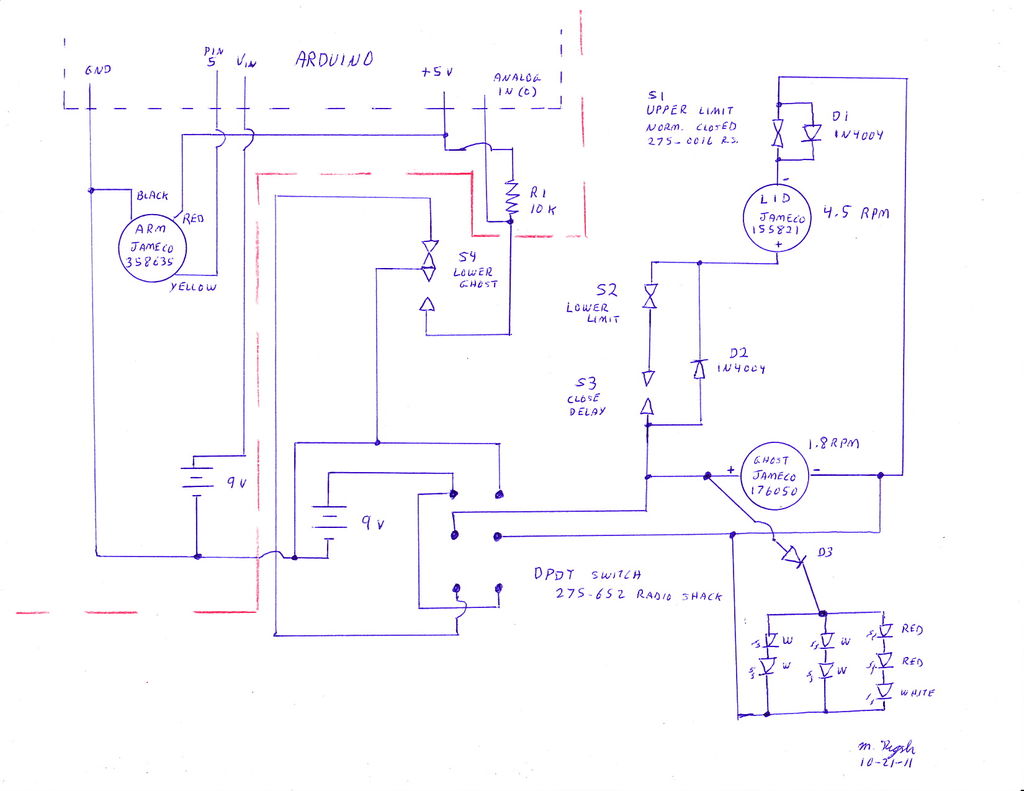
If you choose to build without the “candy flinging arm,” you can eliminate the microcontroller and servo motor (everything to the left and above the red line on the schematic).
Step 2:
Using 1″ x 2″ wood, assemble the base. Top and bottom pieces are 18″ long. The widest spot is 24″ wide. Use a piece of 1/4 inch wood rod and glue to attach the joint between the upper and lower pieces.
Step 3:
Add 11 1/2 inch upright pieces (using wood screws and glue) to form the shell of the box.
Step 4:
Install a cross board to support the motor, 7 1/2 inches from the end.
Step 5:
Mount the motor on the cross board.
Step 6:
Drill two 3/32 inch holes in the coupling shaft and create threads for 4-40 screws with a tap.
Note that I used a yardstick for the ghost spine. This worked for a while, until (during testing) the yardstick failed to contact a limit switch and the torque from the motor split the yardstick into pieces. I suggest using some sort of aluminum channel or angle for the upright piece (I used trim channel).
Attach the shaft coupler to the spine.
Step 7:
Cut a 12 inch long section from a yardstick. Attach a piece of aluminum angle in the center and drill the angle to bolt to the “spine” of the ghost. At the end of this arm, using double sided tape, attach a servo motor.
Servo motor
Three diodes
For more detail: Candy Tossin Coffin using an Arduino
- How do I simplify the project if I do not want the candy flinging arm?
You can eliminate the microcontroller and servo motor if you choose to build without the candy flinging arm. - What material is recommended for the ghost spine instead of a yardstick?
The author suggests using an aluminum channel or angle because the torque from the motor split the yardstick during testing. - Can I use a different material for the ghost spine than wood?
Yes, you can use 3 feet of aluminum trim channel for 1/4 inch plywood or something else stiff for the ghost spine. - What are the dimensions for the base assembly?
The top and bottom pieces are 18 inches long, and the widest spot is 24 inches wide. - How far from the end should the cross board be installed to support the motor?
The cross board should be installed 7 1/2 inches from the end. - What size holes must be drilled in the coupling shaft?
You must drill two 3/32 inch holes in the coupling shaft. - What type of screws are used to create threads in the coupling shaft?
Create threads for 4-40 screws with a tap after drilling the holes. - How is the servo motor attached to the candy flinging arm?
Attach the servo motor at the end of the arm using double sided tape.
