
Summary of Make an Attiny13 based IR proximity sensor
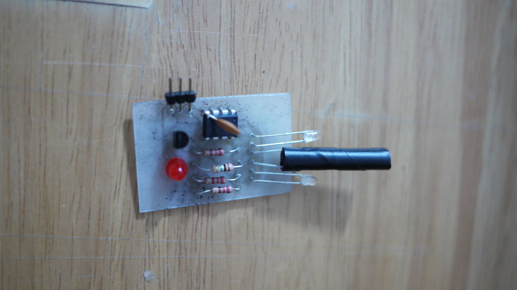
This Instructable shows how to build an inexpensive IR proximity sensor using an ATtiny13 AVR, IR LEDs, and a phototransistor. The ATtiny pulses IR LEDs and compares analog readings with lights on versus off; when reflected light increases the sense output goes high. The design includes a taped straw shroud to block stray IR and an indicator LED. Parts are cheap and the sensor has ~3 inch range, extendable with brighter or more LEDs. Programming is done with an Arduino as an AVR programmer.
Parts used in the ATtiny13 IR Proximity Sensor:
- Phototransistor NPN with filter 5mm (Digikey 475-1439-ND)
- ATTINY13A-PU 8PDIP AVR microcontroller (Digikey ATTINY13A-PU-ND)
- 220 ohm 1/4W resistors (3x) (Digikey CF14JT220RCT-ND)
- 1 M ohm 1/4W resistor (Digikey CF14JT1M00CT-ND)
- 2N3904 NPN transistor (Digikey 2N3904FS-ND)
- IR emitter 3mm 940nm water clear (2x) (Digikey 754-1241-ND)
- Optional 0.1 uF decoupling capacitor (recommended)
- Indicator LED
- Electrical tape
- Plastic drinking straw (shroud)
- Wire, breadboard or soldering materials, jumper wires
- AVR programmer (Arduino compatible)
- Arduino 1.0 software with ATtiny13 core and modifications
This is an extremely cheap IR proximity sensor you can make with a few cheap parts and an AVR programmer. I use an Arduino as my programmer in this Instructable.
This sensor only has a range of about 3 inches. You can easily add more LEDs or brighter ones to extend the range. You can also easily re-arrange the LEDS to detect when a beam is broken as well.
The design takes advantage of a cheap AVR (computer on a chip). The computer pulses the IR LEDs off and on and compares the analog readings from the sensor in each state. When the reading with the lights on is above the reading with the lights off the sense pin goes high indicating the sensor is seeing it’s own (reflected) light. There is an LED on the sense indicator in this design so you can see when the sensor engages. You can connect the signal right to a microcontroller like an Arduino or Picaxe.
This design moves some processing out of your main robot brain and into it’s own node. You may want to debounce the signal, but you don’t have to flash the leds and take the readings. You can also use just one digital pin to take the reading. The sketch is around 700K out of 1024 available.
Why I built this
I’m way out of high school, but this is part of a series of designs related to bringing the robots from the game Robot Oddysey into the real world. I want to allow grade schoolers the same chance to learn robotics I had. So I am working on building really inexpensive robots that can move in 8 directions without turning. The “bumpers” are complete now.
Step 1: Gather Materials
|
Quantity
|
Digikey Part Number
|
Description
|
Cost
|
|
1
|
475-1439-ND475-1439-ND
|
PHOTOTRANSISTOR NPN W/FILTER 5MM
|
$0.53
|
|
1
|
ATTINY13A-PU-ND
|
IC MCU AVR 1K FLASH 20MHZ 8PDIP
|
$0.95
|
|
3
|
CF14JT220RCT-ND
|
RES 220 OHM 1/4W 5% CARBON FILM
|
$0.24
|
|
1
|
CF14JT1M00CT-ND
|
RES 1M OHM 1/4W 5% CARBON FILM
|
$0.08
|
|
1
|
2N3904FS-ND
|
IC TRANS NPN SS GP 200MA TO-92
|
$0.18
|
|
2
|
754-1241-ND
|
EMITTER IR 3MM 940NM WATER CLEAR
|
$0.44
|
|
TOTAL
|
$2.42
|
You will also need
- Electrical tape
- plastic drinking straw
- scissors
- Wire snippers
- breadboard and/or soldering iron
- Jumper wires
- An AVR programmer (any Ardunio compatible will do)
- Ardunio 1.0 software with modifications to program Attiny and the Atiny13 core
Step 2: Create a sensor shroud
Cut off about 1.5″ (4cm) of the straw. Wrap it in electrical tape. Trim the ends and make it neat.
Cut about 1/2″ (8mm) bit of tape and roll it up from the short edge. Fold the roll in half. It won’t stay but put a good crease in it. This will plug the bottom of the sensor and keep stray light out that way.
Step 3: Prepare the sensor
Gently wiggle the sensor into the straw until the base is 1/4″ (5mm) in or so. Push in the folded roll of tape behind it and seal the back with a bit of tape.
Step 4: Wire it up
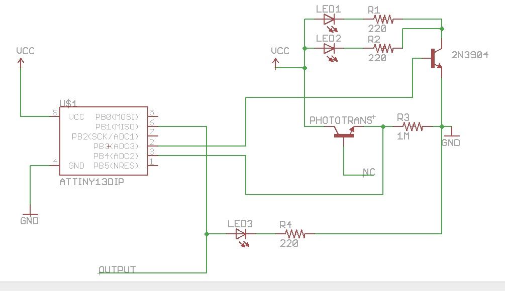
Follow the wiring diagram and keep some notes in mind.
- The chip, LEDs and transistors only work one way around.
- The short leg of the LEDS is connected to the 220 ohm resistors.
- The long leg of the phototransistor is connected to the 1meg resistor.
- You can add more IR emitter/resistor pairs in parallel with the existing pair. Get the basic circuit working first. You could also just use one IR emitter, but 2 seemed to make the readings a lot more stable.
Note: After I did this diagram I discovered a 0.1uf capacitor across the Attiny chip from VCC to GND helps out with stability. It’s recommended to put one across every microchip in a design. It worked reasonably in the breadboard without it, but the circuit board really improved with the addition.
 Attiny13 Proximity Sensor.fzz
- What is the sensing range of this sensor?
The sensor has a range of about 3 inches as built in the article. - Can I extend the sensor range?
Yes, by adding more LEDs or using brighter ones you can extend the range. - How does the sensor detect proximity?
The ATtiny pulses the IR LEDs and compares analog readings with lights on and off; if the reading with lights on is higher the sense pin goes high. - Do I need an AVR programmer to program the ATtiny13?
Yes; the article uses an Arduino as an AVR programmer to program the ATtiny13. - Is a decoupling capacitor recommended?
Yes, a 0.1 uF capacitor across VCC and GND on the ATtiny improves stability. - Can I use only one IR emitter?
Yes, you can use just one IR emitter, though the article found two made readings more stable. - How is stray IR blocked from the sensor?
A shroud made from a taped drinking straw and a taped back plug is used to prevent side light leakage. - Do I need to cut any legs on the phototransistor?
Yes, cut off the middle leg if present; it is not needed and can cause problems. - Can the sensor output connect directly to a microcontroller?
Yes, the sense signal can be connected right to a microcontroller like an Arduino or Picaxe.
