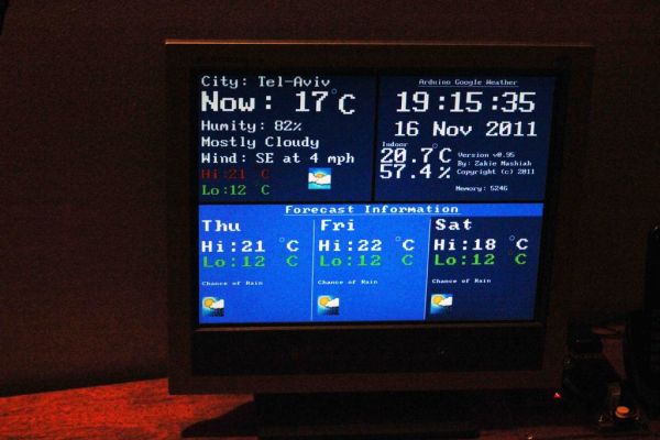
In this project, I am using an Arduino board to show forecast of the weather from Google Weather service on a VGA screen. The display is obviously graphical one, with icons and some colorful text. It is one of those gadgets I wanted to have for some time now – A weather forecasting display that is there just like the wall clock. Yes I know you got nicer looking things on your angry-birds machine… I simply enjoy doing it myself. Had some challenges to overcome, like Arduino has only 2KB of RAM limitation, pretty small for parsing XML data…
Features
• Current and Forecast weather information graphically displayed
• Time display from the internet, using NTP protocol
• Does not require any PC to be involved
• Indoor temperature and humidity display
• Easy to connect and assembly, only Ethernet cable and power
• Supports DHCP for network connection
• Supports both VGA screens and small 3.2″ screens
• Daylight-Saving support through a user button
Some more features include change of background color between night and day for the clocks and change background color of the weather data areas depending on temperatures.
I have a newer version of this at: http://www.instructables.com/id/Weather-Underground-on-graphical-display-with-Netd/
 GW Work.zip164 KB
libraries.zip59 KBStep 1: What is required to build this gadget?
1. Arduino Ethernet Pro (http://www.sparkfun.com/products/10536) or Arduino with Ethernet Shield
2. 4D Systems display (uLCD-32PT) http://www.sparkfun.com/products/10089 or display adaptor (uVGA II)http://www.sparkfun.com/products/10329
3. Arduino I/O headers socket
4. 5x Jumper wires (only 4 required for operation), note the display and display adaptor have male pins and Arduino typically takes female headers.
5. 2GB or less micro-SD (only needs about 150KB)
6. Power Supply
7. Ethernet Cable
8. DHT-22 Temperature and humidity sensor (optional, only if you want indoor temp)
9. Push button (optional)
10. 2x 10K Ohm resistor (optional, only if you want indoor temp)
Also for building the gadget, you will need the following
1. FTDI board, better use 5Volts one like this http://www.sparkfun.com/products/9716 one.
2. PC for programming
3. A micro-SD reader device
4. Soldering Iron
Step 2: Where to buy?
All of the items can be purchased at Sparkfun or your favorite electronic components store. As for the display or display adaptor, they come pre-loaded with one of the firmware types SGC or GFX. It doesn’t really matter which one you buy, as converting from one firmware flavor to the other is very simple task performed by a tool on the PC.
Step 3: How to assembly?
Please read this thoroughly as there could be notes on changes that you might want to do.
1. After purchasing the goods, download software to your PC including:
a. Arduino IDE (I use version 022)
b. 4D Systems tools for programming their adaptors or displays fromhttp://www.4dsystems.com.au/prod.php?id=149
c. Arduino libraries including: NewSoftwareSerial, Arduino Time Library, Ethernet Library
2. Connect your display or display adaptor to the FTDI (Vcc to 5V, GND to GND, Rx to Tx and Tx to Rx, DTR on the FTDI to Reset pin) and the FTDI to USB on your PC
3. Upload the right firmware onto the LCD using PmmC Loader tool from 4D Systems (you need the GFX version)
4. Open the 4D systems Workshop tool; open the program file in the code\4D subdirectory of the ZIP file in this publication. Follow the steps as also shown in the picture for this tool to:
a. Select the right display or adaptor model
b. Select the right COM port (the one the FTDI generates)
c. Select destination as “Flash” and not “Ram” (don’t forget this!)
d. Compile and Load the program to the display/adaptor
5. Place all the necessary Arduino libraries in the right location (if do not exist already)
6. Connect your Arduino to PC
7. Edit the Arduino files to match your time zone and place
a. Edit the file NTPAndTime.cpp and change variable timeZoneSeconds to reflect the difference of your time zone from GMT. If you are west to GMT then use negative values.
b. Change the variable dsSeconds to reflect the standard change from your time-zone
c. Edit the file NetArduino.pde and change the variable weatherDataGetString to match you location (change Tel-Aviv to be your city). I recommend checking in the browser that it works by typing:http://www.google.com//ig/api?weather=yourcity in your browser address field. You should see some XML reply in return if that works.
8. Open the Arduino sketch NetArduino.pde, compile and load the program to your Arduino
9. Connect your micro-SD reader to your PC with the micro-SD in it
10. Save all the files from the microSD subdirectory into the root directory of the micro-SD
11. Safely remove the micro-SD from the reader and place it in the display or display adaptor
12. Disconnect the display and Arduino from PC
13. Connect the display or display adaptor to your Arduino as following:
a. Vcc of the display/adaptor to +5V of Arduino
b. GND of the display/adaptor to one of the Arduino GND connections
c. Connect the Digital I/O pin 5 of Arduino to Rx pin (3rd pin from the right on the adaptor when VGA connector is on the top)
d. Connect the Digital I/O pin 4 of Arduino to Tx pin (2nd pin from the right on the adaptor)
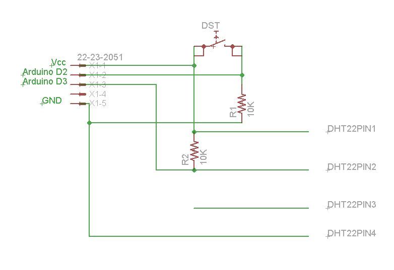
14. Build a small circuit for the push button (see optional DHT sensor circuit too for schema) as following:
a. Push button connects to Vcc on one side and to resistor of 10K ohm on the other side.
b. Other side of the resistor connected to ground
c. Connect Arduino pin 2 to resistor/push-button junction
15. Connect the Ethernet cable to the Arduino
16. Connect the VGA display to the adaptor if you chose to use adaptor
17. Connect power supply to Arduino
18. Enjoy the weather
2. 4D Systems display
3. Arduino I/O headers socket
4. 5x Jumper wires
For more detail: Google Weather on graphical display with Arduino