
Summary of Arduino and Processing IDE Communication Tutorial
This tutorial demonstrates bidirectional serial communication between Arduino and Processing. It enables an Arduino potentiometer to change the color of the Processing window while mouse clicks in Processing control an LED connected to the Arduino.
Parts used in the Arduino and Processing Communication Project:
- Arduino UNO
- 1K potentiometer
- 220 ohm resistor
- LED
- Breadboard
- Connecting wires
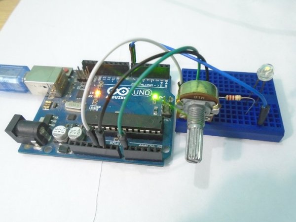
In this tutorial, we will make the communication between the Arduino and Processing. We will make the communication in both the ways, from the Arduino to Processing and from Processing to the Arduino. We will change the color of the serial window in the Processing IDE through the potentiometer value sent from the Arduino IDE. We will turn the LED ON and OFF depending upon the mouse button pressed in the Processing Serial window.
About Processing
Processing is a great source for creating graphics. The Processing IDE works for a computer like the Arduino IDE works for a micro-controller. The Processing IDE is similar to Arduino in terms of structure. It has setup functions and draw functions like an Arduino has a setup and loop function. The Processing IDE can communicate with the Arduino IDE through serial communication. This way, we can send data from the Arduino to the Processing IDE and also from the Processing IDE to the Arduino.
Installing Processing
If you do not have already installed the Processing IDE, then you need to install it first. To install it, go to the link below and download the latest version of processing IDE. https://processing.org/download/
After downloading the latest version, open the Processing IDE setup and install it. After installing, open the Processing IDE and you will see something like this.
Components Required
- Arduino UNO
- 1K potentiometer
- 220 ohm resistor
- LED
- Breadboard
- Connecting wires
Arduino Circuit Diagram
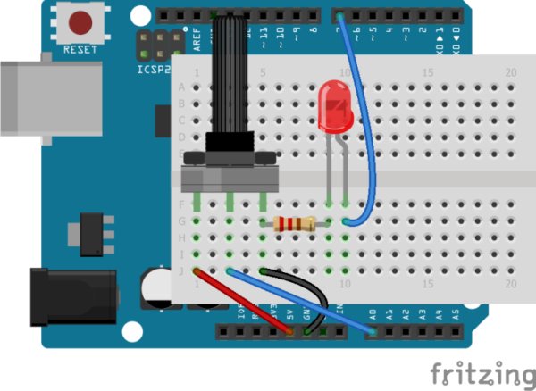
The connections for this tutorial are very easy. Connect the two end pins of the 1k potentiometer to the 5V and the GND pin of the Arduino. Then connect the middle pin of the potentiometer to the A0 on Arduino. Then connect the positive pin of the LED to pin 7 on the Arduino and the negative pin of the LED to the GND pin through the 220 ohm resistor.
How Does it Work?
The Arduino IDE and the Processing IDE will communicate with each other through serial communication. The Processing IDE has a serial library which makes it easy to communicate with the Arduino.
When we move the potentiometer knob, the Arduino will send a value between 0 and 255 to the Processing IDE. The Processing IDE will then change the color of the serial window according to the movement of the potentiometer knob.
Similarly, when we press the mouse button in the serial window of the Processing IDE, the Processing IDE will send a ‘1’ or ‘0’ depending on the left or right mouse button to the Arduino IDE. The Arduino IDE will then turn the LED ON or OFF according to the button pressed.
Read More: Arduino and Processing IDE Communication Tutorial
-
How does the Arduino send data to Processing?
The Arduino sends a value between 0 and 255 from the potentiometer to the Processing IDE via serial communication. -
What happens when the potentiometer knob is moved?
The color of the serial window in the Processing IDE changes according to the movement of the potentiometer knob. -
Can Processing send data back to Arduino?
Yes, the Processing IDE can communicate with the Arduino IDE through serial communication to send data. -
How is the LED turned ON or OFF?
The LED turns ON or OFF depending on the left or right mouse button pressed in the Processing Serial window. -
What values does Processing send to Arduino for the LED?
Processing sends a '1' or '0' depending on which mouse button is pressed to control the LED state. -
Which pins connect the potentiometer to the Arduino?
The two end pins connect to 5V and GND, while the middle pin connects to A0 on the Arduino. -
Where is the LED positive pin connected?
The positive pin of the LED is connected to pin 7 on the Arduino. -
Does the Processing IDE have functions similar to Arduino?
Yes, the Processing IDE has setup functions and draw functions similar to the Arduino setup and loop functions.
