
Summary of Bidirectional Motor Control Using Arduino
One simple bidirectional motor control uses a DPDT relay plus two transistors and two microcontroller pins: one pin/transistor for on/off (high-current transistor like TIP120 or a FET/SPST relay for heavy motors) and one pin/transistor for relay coil/direction (e.g., 2N3904). The DPDT relay reverses motor polarity to change direction. Diagrams match Jameco 174378 / Radio Shack 275-249A relay pinouts. Example Arduino code runs the motor two seconds each direction with 10 ms pauses to reduce switching noise.
Parts used in the DPDT relay bidirectional motor control:
- DPDT relay (e.g., Jameco 174378 or Radio Shack 275-249A)
- 2N3904 transistor (direction control)
- TIP120 transistor (on/off control) or equivalent high-current switch
- Microcontroller with two output pins (e.g., Arduino or Stamp)
- Motor
- Diodes or flyback protection for relay and motor (as shown in typical schematics)
- Wiring, breadboard or PCB for layout
- Power supply appropriate for motor and relay coil
One of the simplest ways to get a motor to turn in both directions is by using a double-pole, double-throw (DPDT) relay. Along with the relay, this hookup requires two transistors and two Stamp pins, one for on/off control and the other for direction control.
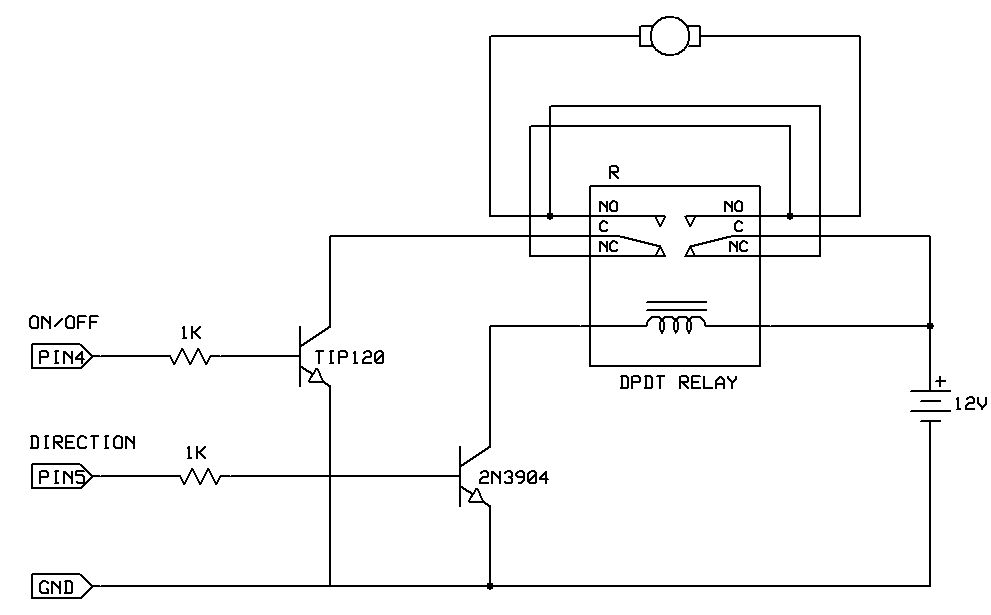
The diagram below contains the schematic for this setup. The DPDT relay is switching the direction of current flow through the motor to get it to turn in either direction. The direction control transistor can be a 2N3904 because most relays require much less than 100 mA through the coil to trip the contacts. A TIP120 can also be used for the direction control. A TIP120 is required for on/off control because it must be able to handle the motor currents. For very high current motors, replace the TIP120 on/off control with a low on-resistance FET or with a SPST relay. In the diagram, the location of the relay pins matches a top view of the DPDT relay sold in the Robot Store (Jameco 174378) and the Radio Shack 275-249A relay.
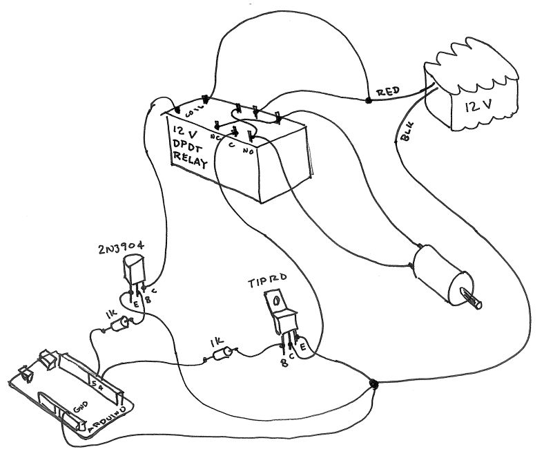
The next diagram illustrates how to lay this circuit out. The pinouts shown are correct for the Jameco 174377 and Radio Shack 275-249A relays.
Here is an example Arduino program that runs the motor for two seconds in one direction and then two seconds in the other direction.
The 10 ms pauses are to minimize noise spikes caused by turning off the motor and the relay at exactly the same time.
For more detail: Bidirectional motor control Using Arduino
- How does the DPDT relay change motor direction?
The DPDT relay switches the direction of current flow through the motor, reversing its rotation. - Can I use a 2N3904 for the direction control?
Yes, the direction control transistor can be a 2N3904 because most relays require much less than 100 mA through the coil. - What transistor is required for on/off control?
A TIP120 is required for on/off control in the example because it must handle the motor currents; for very high current motors use a low on-resistance FET or a SPST relay instead. - Do the diagrams match specific relay pinouts?
Yes, the diagrams show pinouts correct for the Jameco 174378 and Radio Shack 275-249A relays. - What microcontroller resources are needed?
The hookup requires two microcontroller pins: one for on/off control and one for direction control. - Why are 10 ms pauses used in the example program?
The 10 ms pauses minimize noise spikes caused by turning off the motor and the relay at exactly the same time. - Can a TIP120 be replaced for very high current motors?
Yes, replace the TIP120 on/off control with a low on-resistance FET or with a SPST relay for very high current motors.