Summary of Balancing Instructable Robot using arduino
This Instructable describes building a self-balancing robot styled like the Instructables Robot using an Arduino UNO, MPU6050 gyro/accelerometer, PID control, DC geared motors, and an L298 motor driver. It covers chassis fabrication from acrylic or hylam sheet, motor mounting, wiring, and PID tuning to maintain balance, plus lessons and applications of control systems.
Parts used in the Self Balancing Instructable Robot:
- Arduino UNO
- L298 Motor Driver Module
- DC Geared Motor (300RPM)
- MPU6050
- Gear Motor Wheels
- Jumper Wires (Male to Female)
- USB Cable
- 4-Pin Connector
- 9V Battery
- 9V Battery Power Connector
- 10k Potentiometer
- Potentiometer Knobs
- Acrylic Sheet (or Hylam/Bakelite Sheet)
- 90° Clamp or L-Clamps
- Cable Ties
- Soldering Iron
- Solder Wire
- Double Sided Tape
- Yellow Chart Paper
- Sketch pens
- Scissors
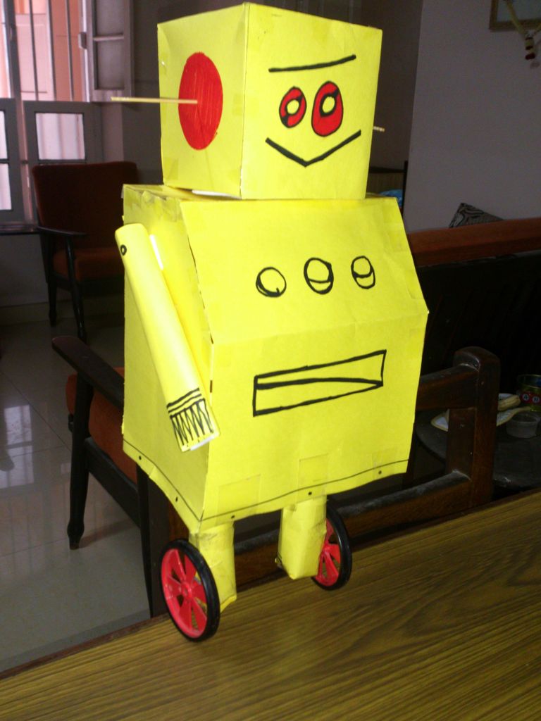
In this Instructable I wanted to show to you how to make a self balancing robot. What makes it unique is that its exterior is made to look like the Instructables Robot. Internally it works in the principle of PID, it is a very popular control system for maintaining a variable from fluctuating. In this instructable I have used the MPU6050 which is a gyroscope and an accelerometer in a single package. The gyroscope is used to find the angular orientation and the acceleration. For our application we just need the gyroscope data. To start off I will discuss the various applications and knowledge obtained from this project. Please vote for my entry in the “Instructable Robot Contest” if you find this instructable good.
Project-Based Learnings:
- Knowledge of how to use the MPU6050 module.
- How to implement the data to balance the robot.
- How to implement control systems to your projects.
____________________________________________
Applications:
- This Instructable serves as an introduction to the various Control Systems.
- These Control Systems are also implemented in Segways and The Ball Balancing Robot.
- These Control Systems are also applied to PID Furnace Temperature Control, The Line Following Robot, etc.
____________________________________________
Proportional-Integral-Derivative System Advantages:
- This Control System should be used when the controlled element needs precise control.
- This balancing robot can be easily made by a Novice Arduino Programmer using this Control System.
- The tuned PID system is very flexible over a range of environments (i.e. balancing even when weight is added).
____________________________________________
This control system’s efficiency depends on the tuning of three variables namely the Proportional constant, Integral constant and Derivative constant, So once you tune the variables accurate control of the robot is achieved. I have provided most of the instructions for making the robot. This robot is in the intermediate level of robotics so beginners shouldn’t get frustrated because it for very challenging for Me!!!
Step 1: Parts & Materials
The material needed to make this balancing robot can be grouped into two categories as shown below:
Electronic Components:
____________________________________________
Other Parts:
____________________________________________
Please note that I have not used Acrylic Sheet as mentioned but Hylam Sheet(Bakelite Sheet). It is very much similar to acrylic but more rigid and easier to cut. It is commonly used in India for Switchboard Boxes. It may or may not be available in your Country so I mentioned it as an Acrylic Sheet.
Step 2: Making The Robot Chassis
This step is for making the chassis parts which form the base of the robot. As I mentioned earlier I have not used the acrylic sheet but a Hylam Sheet. The base consists of two strips to which the motor is mounted and a rectangular base on which these strips are mounted in perpendicular. To prepare the Body follow these instructions.
Step 1:
In this Step, I cut the strips that support the motors. I’ve cut them with dimensions of 2cm by 8cm. This material is much stronger than the acrylic sheet.
Step 2:
When the sketch has been drawn, cut the pieces out using a Hacksaw or a Jigsaw cutter. The cutting process will produce a lot of dust. Cut the sheet in a well ventilated room.
Step 3:
Next comes the base which supports the two strips. Draw a Rectangle of about 14cm in width and 18cm in length. Then draw the mid-line for the base along the width as shown in the diagram. This line will serve as a guide line for fitting the strips.
Step 4:
Cut out this drawn part using the Hacksaw or the Jigsaw cutter as shown. Use a marker for reference and clean the board later to remove the marker lines.
Step 5:
Next draw two vertical lines as shown in the diagram. These lines are used for aligning the clamps of the motor. With this step we have finally completed the chassis components. The next step deals with the motor and wheel assembly.
Step 3: Attaching the motors
After cutting the chassis components next comes, assembling the motors with the strips we cut earlier, then attaching these strips to the bigger piece we cut using L-clamps. The motors need holes for the wires to pass through so they should also be cut in addition to the clamp holes.
Step 6:
Cut some double sided tape and stick it to one end of the strip as shown in the diagram. This method involves no clamping with nuts and bolts.
Step 7:
Remove the double sided tape top paper cover to reveal the other adhesive side of the tape. Place the motor on the tape so that it is parallel to the strip.
Step 8:
Then tighten the motor to the strip using cable ties. This ensure that the motor is firmly clamped to the strip.
Step 9:
Cut off the excess and Cable tie wire using either a wire stripper or scissors.
Step 10:
Fit the wheel into the motor and tighten the joint using a screw as shown.
____________________________________________
There you go you have completed mounting the motor onto the strip. Repeat the procedure for the second strip and you would have obtained two of the Instructable strong>Robot’s legs with wheels. The final diagram shows the completed legs.
Step 4: Finishing the Chassis
With this page we will complete the chassis of the Instructable Robot. The prepared chassis is very rigid and stable and is capable of handling the weight of the battery and the electronics. The motors in the pictures are dirty, please excuse it since I have been using them for my other projects.
Step 11:
In this step I use a L-Clamp which is basically a piece I have in my childhood engineering set. You will be easily able to find out L-Clamps, a link to some clamps is also provided. Anyway place the clamp on top of the free end of the strip. Then mark the holes of the clamp using a marker.
Step 12:
Repeat the same procedure for the other motor strip. You will obtain two strips with holes marked and ready for drilling.
Step 13:
This step shows Me drilling the holes on both the motor strips. The holes are made by a 4mm drill-bit.
Step 14:
Before mounting the clamps on the strips, place the clamps on the main board as shown in the diagram. Then mark the holes using a marker for drilling.
Step 15:
This step shows Me drilling the holes on the base of the chassis.
Note:
I only drilled two holes in the previous picture but another hole is needed for the wires to pass through the chassis. So please make another hole.
Step 16:
On completing all these steps you will obtain the following assembled parts as shown in the diagram.
Step 17:
I have not provided any pictures of tightening the nuts and bots but once screwed in, it will look as shown in the diagram.
____________________________________________
After completing all these steps the finished chassis will look as shown in the last Figure. The chassis houses the Battery, Ultrasonic Sensors and The Electronics.This ends the mechanical work needed for this project.
Step 5: Mounting the motors to the driver.
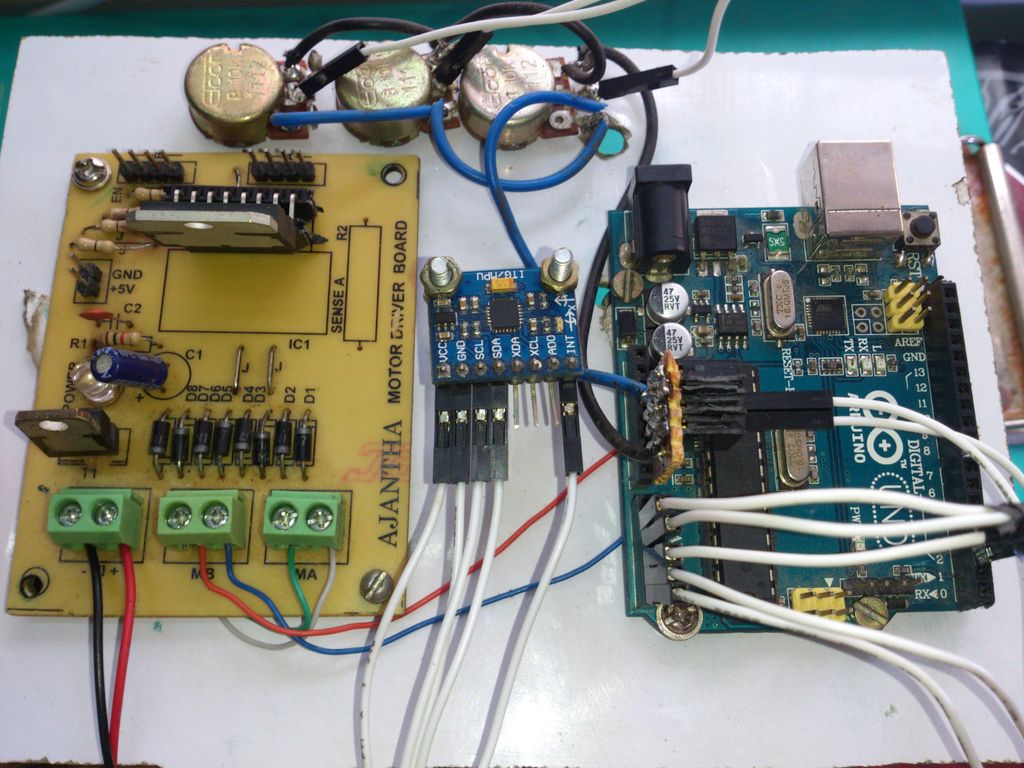
Lets move on to wiring the electronics for the robot. The next few steps will have some Fritzing sketches, some additional images and a little description of the module we are using. So that you are aware of both the working and how to operate the module. The steps below show us how to wire the motors and fix the battery.
Step 18:
In this step I solder the wires to the motor terminals.
Step 19:
Pass the wires through the extra hole we drilled in the clamp as shown in the figure.
Step 20:
Place the module on the base and mark the holes using a marker.
Step 21:
In this step I make the using using a 4mm Drill bit.
Step 22:
Fix the module to the base using some nuts and bolts. This firmly fixes the module to the base.
Step 23:
Connect the motors to the motor terminals of the module and the 9V battery connector to the Power terminals of the Module.
Step 24:
Finally screw the terminals using a Screw-driver so that the wires are fixed.
For more detail: Balancing Instructable Robot using arduino
- What sensor is used to measure orientation in the robot?
The MPU6050 gyroscope and accelerometer module is used; the gyroscope data is used for angular orientation. - What control method is used to keep the robot balanced?
The robot uses a Proportional-Integral-Derivative (PID) control system. - Which microcontroller is used to build the robot?
An Arduino UNO is used in the project. - Which motor driver is used to drive the motors?
The L298 Motor Driver Module is used to drive the DC geared motors. - What type of motors are used for the wheels?
DC Geared Motors (300RPM) with gear motor wheels are used. - What materials are suggested for the chassis?
Acrylic sheet is suggested; the author used Hylam (Bakelite) sheet as an alternative. - How are the motors attached to the chassis strips?
Motors are placed on double sided tape, tightened with cable ties, and excess ties are cut off. - What power source is used for the electronics and motors?
A 9V battery with a 9V battery power connector is used to power the module and motors. - What tools are required to cut and assemble the chassis?
A hacksaw or jigsaw for cutting, a drill with a 4mm bit, and basic tools for marking and fastening are required.