
Summary of Hacking a Powerglove using Arduino
This article details how to hack a Nintendo Powerglove by tapping into its flex sensors, buttons, and D-pad to add custom functionality like an accelerometer. The project involves disassembling the glove, replacing diodes with 10k resistors to interface with the sensors, and connecting an Arduino microcontroller for data processing. Optional enhancements include adding vibration feedback via an Ardumoto shield and mounting the electronics using ABS sheets and a battery holder.
Parts used in the Hacked Nintendo Powerglove:
- Nintendo Powerglove
- Screwdriver
- Wire
- Arduino microcontroller
- USB cable
- 4 - 10k resistors
- ABS sheets
- Nuts and bolts
- Accelerometer or other sensor
- Xbee with shield
- 9v Battery
- Ardumoto shield
- Vibrating motor
First of all lets get this out of the way… It’s so bad
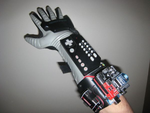
This is going to be showing how to hack the Nintendo Powerglove. By hack I mean tap into the flex sensors and use the buttons and d pad and add anything you want. In my case I added an accelerometer.
I got mine from Ebay for around $40. These gloves have 4 flex sensors similar to these: http://www.sparkfun.com/products/8606
Now these are $12 a piece, it’s way cheaper to buy a Powerglove for 4 sensors and get a bunch of other awesome things then buy 4 of these.
Step 1: Materials
Materials:
Screwdriver
Wire
microcontroller (i used Arduino)
USB cable
4 – 10k resistors
Optional:
ABS sheets
Nuts and bolts
Accelerometer or whatever sensor
Xbee with shield
9v Battery
I also have an Ardumoto shield with a vibrating motor for a feedback system
Step 2: Take it apart
This is kind of tricky if you don’t know where the screws are. Don’t loose them either!
Just fallow the pictures:
Step 3: Flex Sensors
Now its time to tap into the flex sensors. Flex sensors are variable resistors which mean the more you flex the more the resistance. You can then read that and map that value to anything you want. There are two wires coming from each sensors so we have 8 wires.
This website shows a good wiring diagram and explanation for it all: http://www.makingthings.com/teleo/teleo/cookbook/bendsensor.htm
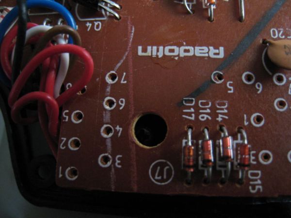
We want to open up the palm to expose the board. Once we have that find where the sensors attach to the board. There will be 4 diodes by there. We are going to desolder the diodes and replace those with the 10k resistors. We will be attaching the positive to one of the two wires of each sensor. We well then attach ground to the resistors and attach wires from the second sensor wire. Pictures will help explain this a lot better.
Step 4: Attach Arduino (optional)
I made a custom extension coming off the glove to hold the arduino. I did this with an ABS sheet and a heat gun. Pretty much heat it up and form it around your arm to get the shape. Then drill holes and attach to the glove with some nuts and bolts. I also made a custom 9v battery holder out of this stuff too.
Step 5: Wire management
I tried to make this look as nice as I could. What I did was run the wires from the palm board to the forearm board then out of that to the arduino. This worked the best for me and it was easy.
Wire
Arduino
USB cable
4 – 10k resistors
For more detail: Hacking a Powerglove using Arduino
- How can I tap into the flex sensors of a Powerglove?
You must open the palm to expose the board, desolder the four diodes near the sensors, and replace them with 10k resistors. - What is the function of the flex sensors in this project?
Flex sensors act as variable resistors where resistance increases as the sensor is flexed, allowing values to be mapped to any desired output. - Can I add an accelerometer to the Powerglove?
Yes, the author added an accelerometer and notes that you can add anything you want to the system. - What materials are required to build a custom mount for the Arduino?
You need ABS sheets, a heat gun to shape the sheet around your arm, nuts, bolts, and a drill to attach it to the glove. - How do I manage the wiring between the palm and the Arduino?
The best method described is running wires from the palm board to the forearm board and then out to the Arduino. - Is it cheaper to buy a Powerglove or individual flex sensors?
Buying a Powerglove is cheaper because it provides four sensors for around $40, whereas buying four individual sensors costs about $48. - How can I implement a feedback system in the glove?
You can use an Ardumoto shield connected to a vibrating motor to create a feedback system. - What optional components can be added to the project?
Optional additions include an Xbee with shield, a 9v battery, and a custom battery holder made from ABS sheets.