Electrical Components
The electrical components are the five motors and their associated circuits, the buttons, and the thermocouple.
The Circuit
We are controlling two stepper motors, three servos, a thermocouple, and a set of buttons using an Arduino. Our final circuit diagram looks like this:
Building the Circuit
1. Stepper motors: The first step we tackled when building the circuit was the stepper circuit (for the lifter and the extruder). We chose steppers over servos or DC motors because we needed a lot of torque, which made compatible servos much more expensive, and we needed feedback, which ruled out DC motors. We chose to build our own stepper drivers using H-bridges (L293D) because we were worried about budget constraints and stepper drivers are pretty expensive. We were able to build our own drivers because our steppers draw a relatively low current and we can access the Arduino stepper library to make the software component easier. The drawback was that we required four Arduino pins to drive each stepper. We attempted to use a different circuit (Figure 2) which would only require two Arduino pins per motor, but the steppers did not turn as smoothly, which was important for the extruder.
2. Servo motors: We then worked on powering the servos. Figure 3 shows how each servo was wired. This was the first time we encountered power problems because the servos were drawing too much current to be supplied by the 5V pin of the Arduino. We solved this problem temporarily by disengaging each servo in software immediately after it finished turning to prevent more than one servo from turning at a time. We attempted to regulate our 12V supply to 5V, but we encountered the same current issues (the regulator we had access to was current-limited to 150 mA). Due to time/material constraints, we decided to power the servos using four AA batteries.
We chose to get continuously rotating servos because two of our systems (the shaker and the stirrer) needed to rotate 360 degrees. We didn’t want to hack a servo because we had no experience in this area, and continuous servos were relatively inexpensive. We ended up just buying three continuous servos (one for the tip exchanger as well) even though the tip exchanger would have benefitted from being positioned control rather than velocity controlled. We did manage to calibrate the servo and implement a software hack to make 180 and 360 degree turns by turning the servo for a set amount of time.

3. Combining: The biggest problem we had when combining the stepper and servo circuits was in the current being drawn. We kept burning out Arduinos because our five motors needed too much power. We ended up fixing this problem (for the most part) by powering all the motors externally, through batteries or a 12V wall adapter. We first combined the circuits on a breadboard, so that we could fully test the motors and modify as needed.
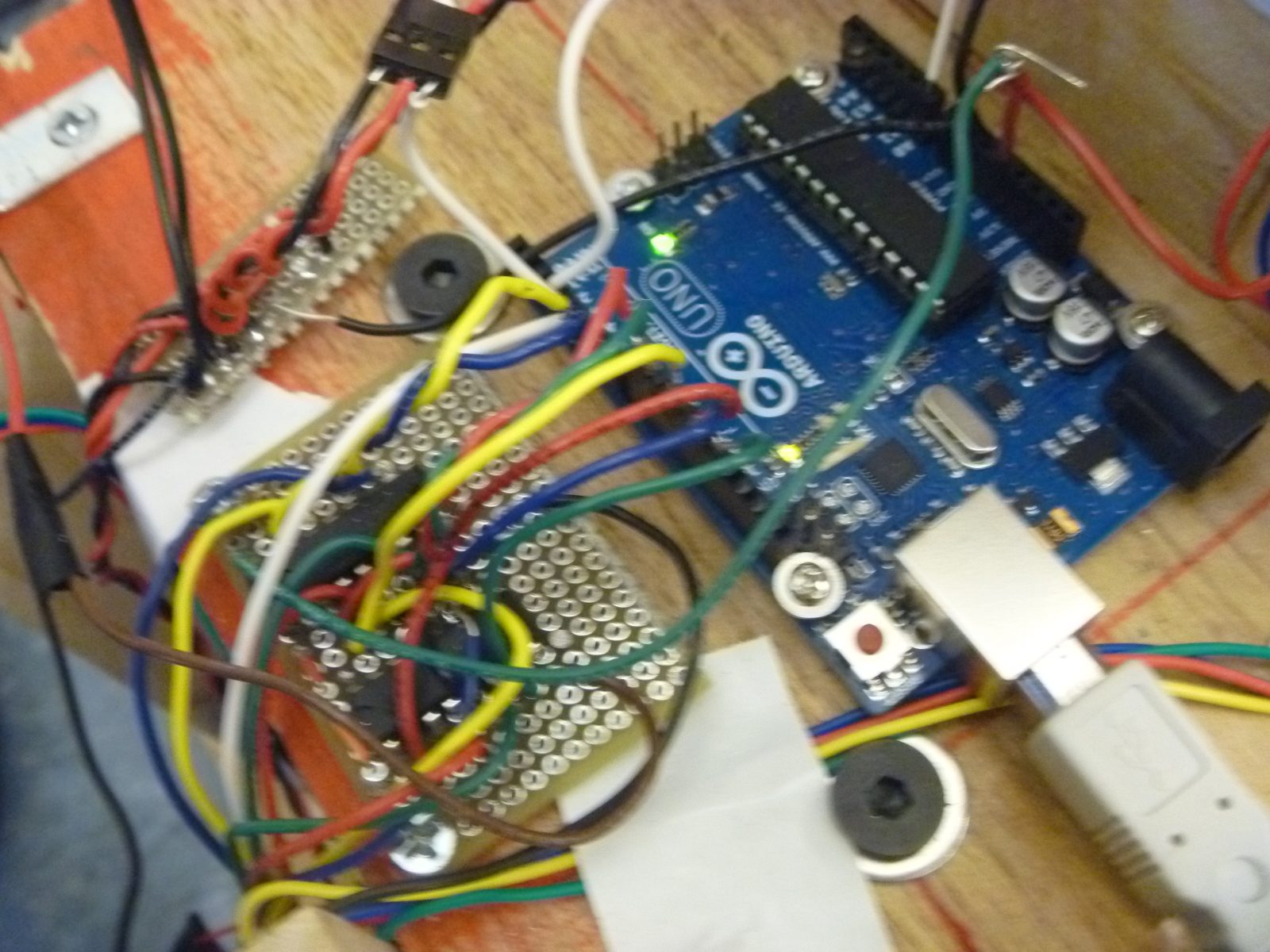
After we were satisfied that all of the motors worked when attached to their respective systems (discussed in more detail in the Mechanical section), we moved the circuit to a more permanent form – on a proto-board. The proto-board is also easier to mount on the actual system than a breadboard.
For more detail: Chur-Robot