Summary of 8 Channel Relay Board Using Arduino
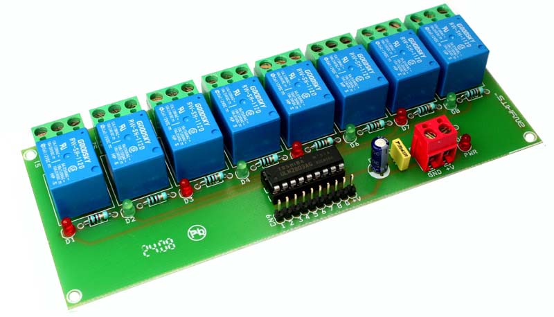
8 Channel Relay Board provides an easy way to connect eight SPDT relays for switching in microcontroller and analog projects. It supports 12 VDC supply, TTL/CMOS trigger levels, LED indicators per channel, and screw terminals for outputs and power. The board includes a header for triggers, four mounting holes, and measures 152 mm x 60 mm.
Parts used in the 8 Channel Relay Board:
- 8 SPDT relays (5 A @ 230 VAC)
- PCB (152 mm x 60 mm)
- Header connector for power and trigger voltage
- Screw terminal connector for relay outputs and auxiliary power
- LED indicator for each channel (8 LEDs)
- Power supply input (12 VDC)
- Mounting hardware points (four 3.2 mm holes)
- Trigger circuitry supporting 2 ~ 15 VDC
| Description |
|
|
8 Channel Relay Board provides an easy and practical method to connect 8 relays for switching purposes in your project. Voltage level support for both TTL and CMOS is provided by the input. Simple interface for projects using Microcontrollers and analog circuits.
Specifications:
Input supply 12 VDC @ 336 mA
Output eight SPDT relay
Relay specification 5 A @ 230 VAC
Trigger level 2 ~ 15 VDC
Header connector for connecting power and trigger voltage
LED on each channel indicates relay status
Screw terminal connector for easy relay output and aux power connection
Four mounting holes of 3.2 mm each
PCB dimensions 152 mm x 60 mm
For more detail: 8 Channel Relay Board Using Arduino
- What supply voltage does the board require?
The board requires 12 VDC input supply at 336 mA. - How many relays are on the board?
The board provides eight SPDT relays. - What is the relay switching rating?
Each relay is rated at 5 A at 230 VAC. - What trigger voltage levels are supported?
The trigger level range is 2 to 15 VDC, supporting TTL and CMOS. - How are outputs and power connected?
Outputs and auxiliary power use a screw terminal connector. - Is there an indicator for relay status?
Yes, there is an LED on each channel indicating relay status. - Does the board have mounting holes?
Yes, it has four mounting holes of 3.2 mm each. - What are the PCB dimensions?
The PCB measures 152 mm by 60 mm.