Summary of 7-Segment NeoPixel Clock With Countdown Timer
This Instructable guides users in building a 7-segment NeoPixel Clock with a countdown timer, inspired by the authors' parents' fitness room needs. The project combines timekeeping and workout timing features using an Arduino Pro Mini, IR remote control, and customizable lighting. It supports single or recurrent timers with break intervals, offering a dedicated solution for exercise tracking without relying on phones.
Parts used in the 7-Segment NeoPixel Clock:
- Arduino Pro Mini 5V
- 4x NeoPixel ¼ Ring 24-Bit RGB LED
- 1.2" 4-Digit 7-Segment Display w/I2C Backpack
- DS3231 RTC Module
- Piezo Buzzer PS1240
- IR Receiver Sensor 38kHz
- IR Remote
- Power Adapter 5V 2A
- 2n2222 Transistor
- 1k Resistor
- 1000 uF Capacitor
- CR2032 3V Battery
- Flexible 28AWG wire
- Acrylic Sheet
- E6000 glue
- Printable adhesive vinyl sheets
- Black Spray Paint
- Printer
- Hot glue gun
- Exacto knife
- Soldering iron + Solder
In this Instructable, my twin brother, Sunyecz06, and I will show you how to make a 7-segment NeoPixel Clock with Countdown Timer. The inspiration for this project began with our parents and their fitness room. While they have an older digital clock in the room, it has no functionality other than telling the time. And oftentimes, our parents will use their phones as a countdown timer for their workouts but they have no dedicated stand for it, so situating it in the room is cumbersome and tedious. My brother and I always try to make something for our parents for Christmas and we came up with the idea of creating an “Exercise Clock” that not only adds a modern clock into the room but also incorporates a countdown timer so that our parents will not have to fumble with their phone timers anymore. While we designed the clock with exercise/fitness in mind, this can be created and placed in a variety of other locations!
We are very pleased with how the clock turned out and our parents love it! Here is a quick rundown of some of the features of our exercise clock!
– 7-segment display that shows current time of day and illuminates NeoPixel ring according to the current minute of the hour
-IR sensor that enables that user to adjust clock/timer settings from anywhere in close proximity with IR remote
-Countdown timer function that allows user to set a countdown timer.
-Recurrent countdown timer that will loop a timer infinitely with a user-input break in between. E.g. HIIT workout that may require a 1 minute timer with a 30 second break in between sets
-Piezo buzzer that buzzes when timer reaches 0. Also provides auditory feedback whenever a button is pressed on the IR remote
If you are interested in seeing how we made this project or you want to make one for yourself, please follow along! If you have any questions, leave them in the comment section below and we’ll try our best to respond quickly!
Supplies
Electronics:
–4x NeoPixel ¼ Ring 24-Bit RGB LED
–1.2” 4-Digit 7-Segment Display w/I2C Backpack
–IR Receiver Sensor 38kHz (Salvaged ours from an iHome iH9 unit)
–IR Remote (Salvaged ours from an iHome iH9 unit)
-Power Adapter 5V 2A
-2n2222 Transistor
-1k Resistor
-1000 uF Capacitor
-CR2032 3V Battery
-Flexible 28AWG wire
Miscellaneous:
-3D printer (optional)
-Acrylic Sheet cut into desired diameter
– E6000 glue
-Printable adhesive vinyl sheets
-Black Spray Paint
-Printer
-Hot glue gun
-Exacto knife
-Soldering iron + Solder
-Tools (wire cutters, scissors, needle nose pliers)
Step 1: Circuit Diagram and Testing the Electronics
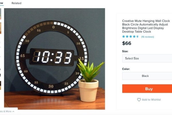
We were basing our idea off of a unique clock design we had seen while perusing the internet. In order to replicate something similar to this, we needed some essential components. Those included: an Arduino to run the program, an RTC module to obtain real time clock data, a NeoPixel ring for display, and a 7-segment display to show the time/timer digitally. We wanted our parents to be able to adjust the clock from a distance so we chose to incorporate an IR receiver/remote. Finally, we wanted to add some type of auditory buzz when the timer completed, so we incorporated a piezo buzzer.
Circuit Diagram:
We chose to use EasyEDA to create our schematic. A PDF version of the schematic is available in the attachments. Of note, both the RTC module and the 7-segment w/backpack use the I2C protocol. On the Arduino Pro Mini, those pins correspond to A4 (SDA) and A5 (SCL). The IR receiver is connected to pin 2 as that pin is useable as an external interrupt. The NeoPixel data input can be connected to any digital pin and we chose pin 6 as that is what Adafruit uses by default in their example codes. Finally, we connected the piezo buzzer to pin 3 and wired it to the base of a 2n2222 transistor to increase the volume of the buzzer.
Wiring and Testing The Electronics:
We began by wiring the components on a breadboard per the schematic and tested the individual components to ensure they were working properly. We will go through each main component below
-NeoPixel Ring:
o The NeoPixel ring was delivered in 4 segments that required soldering each segment arc together to form the actual ring. It is important to leave one bridge of pads unsoldered and to solder the free ends of the accompanying 3-wire JST to the data, power, and ground pins respectively. Those pins can then be wired into pin 6, +5V, and GND on the Arduino. We also connected a 1000 electrolytic capacitor between +5V and GND per the Adafruit recommendations.
o Adafruit has an excellent NeoPixel Uberguide available on their website that runs through basic connections, software installation, and examples. We used this quite a bit to understand the NeoPixel basics as this was our first time utilizing such a component. After soldering and wiring the NeoPixel to the Arduino, head the Uberguide for more info on installing the Adafruit NeoPixel library within the Arduino IDE. We ran the “strandtest” example to ensure our NeoPixel ring was working properly.
-IR Receiver/Remote:
o We had an old iHome iH9 unit lying around that we decided to take apart. We salvaged the IR sensor and remote from that and chose to use it for this project. However, really any IR receiver and remote will do the trick. Adafruit has cheap IR sensors/remotes that will work just fine as well as example codes on how to set them up.
o For our remote, we first needed to determine the NEC codes for each button press. In order to do that, we downloaded the IRsmallDecoder libraryby Luis Carvalho in the Arduino IDE and ran the “HelloNEC” example code. This allowed us to get the unique hexadecimal value for each button press on our remote.
-7-Segment Display w/i2c Backpack
o We purchased the 1.2” 7 segment LED display with backpack and used the Adafruit tutorial to solder it together and run example codes.
o The backpack is simple to connect to the Arduino and after downloading the Adafruit LED Backpack Library and running the “sevenseg” example code, we were able to see the 7-segment working correctly
-DS3231 Real Time Clock Module
o This RTC module already has breadboard friendly pins so connecting it to the Arduino for testing is very easy to do. We also added a CR2032 3V battery to the terminal as well
o To test, we downloaded the RTClib library in the Arduino IDE and ran the “ds3231” test code to ensure the component was working and printing the current and correct date/time.
Step 2: Main Arduino Program
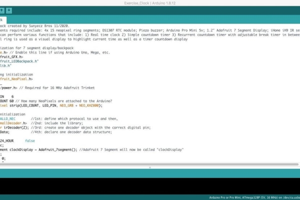
After ensuring the individual components worked properly, we were able to move on to coding the main program. We will include our program in the attachments should you want to use/alter our code and tried to heavily comment it so that you can better understand our thinking. Because of this, we will not go line-by-line explaining our code here but rather highlight some of the important concepts/features. We had a simple set of goals that we wanted to accomplish.
Goals:
-Display current time on 7-segment display
-Utilize NeoPixel ring in time of day/countdown timer display
-Set a single countdown timer
-Set a recurrent countdown timer with adjustable break timer
-Utilize IR Remote/Receiver
-Use buzzer to indicate button press/end of timer
For the program, the first thing is to ensure that the proper libraries are installed. The easiest way to do this is by downloading them through the Arduino IDE via “manage libraries”. These include:
Within void loop(), we essentially created 4 different “pages” in order to accomplish our goals. These include a “Clock Home Page”, a “Timer Setting Page”, a “Timer Countdown Page”, and a “Break Timer Setting Page”. Again, we won’t go into too much detail but we’ll highlight what each ‘page’ accomplishes with respect to the hardware.
– “Clock Home Page”
o Displays current time on 7-segment display and blinks semi-colon every second
o Lights up the NeoPixel ring corresponding to minutes on the hour (E.g. at 3:10, the first 10 LED’s in the NeoPixel turn red, with the remaining staying white)
o Listens for the Timer button to be pressed on the IR remote. If pressed, will take the user to the “Timer Setting Page”
– “Timer Setting Page”
o Allows user to set desired countdown timer via the IR Remote in increments of 05 seconds, 1 minute(s), and/or 10 minute(s).
o Lights up the NeoPixel ring according to the seconds/minutes selected for aesthetics purposes
o Listens for the IR Remote to be pressed. Various options from here include:
– Home button – returns to “Clock Home Page”
– :05 second button – adds 05 seconds to the timer
– 1 minute button – adds 1 minute to the timer
– 10 minute button – adds 10 minutes to the timer
– Reset button – resets timer back to 0
– Clock snooze button – takes user to “Break Timer Setting Page”
– Loop button – lights up colon and signals that countdown timer will be in recurrent loop mode. If off, countdown timer will run through once and go back to “Clock Home Page”
– Play button – starts countdown timer by running a 3 second countdown and taking user to “Timer Countdown Page”
– “Timer Countdown Page”
o Counts down the pre-set timer from the user on the 7-segment display
o Subtracts an LED on the NeoPixel ring corresponding to the current second/minute.
o When timer hits 0, either takes user to “Clock Home Page” or begins break timer depending on if loop was turned on by the user
o Listens for the Home button to be pressed on the IR Remote in order to stop the timer and be taken back to “Clock Home Page”
– “Break Timer Setting Page”
o Allows the user to set the desired break timer that will run in between sets if the loop option was turned on by the user. The same features that are present in “Timer Setting Page” are present here as well regarding setting the break timer and listening for button presses from the IR remote
Finally, we have included a User Manual that provides instructions on how to set the countdown timer and what each button on the IR Remote does when pressed. We will include that in the attachments as well.
Step 3: 3D Print the Enclosure
Before wiring up everything, we needed to design and 3D print the enclosure. We had a few design considerations but were ultimately inspired by this commercially available clock. However, we wanted it to look more like a traditional analog clock with numerals around the outside of the neopixel ring. We also wanted a way to separate each individual pixel and hide the gray faceplate of the seven segment display. We came up with the idea of using plexiglass or acrylic as the faceplate for all of the electronics. We could then use a “stencil” and paint on the numbers and cover everything else for a more professional look.
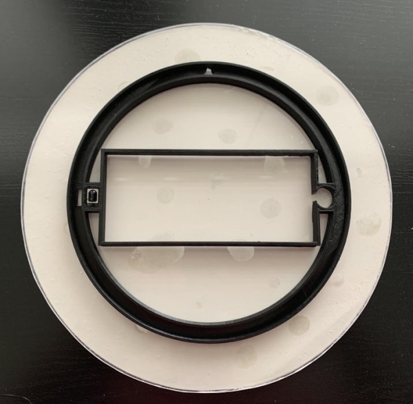
With this idea in mind, it is time to design the enclosure. We used Fusion360 for all of the modeling. Because the acrylic would make up the faceplate, we just needed to design the backing to cover up the electronics. We started designing the ring to house the neopixels. We then made a rectangle cutout that fit the seven segment display. We decided the piezo and IR sensor could be included in the part that joined the ring to the rectangle and made appropriate cutouts to fit both on either side of the seven segment display. There would be enough room to solder the rest of the electronics behind the seven segment display and the back plate was designed to cover the back. We wanted the ability to maintain access to the Arduino and RTC battery and an appropriate cutout for the coin cell battery, power cable, and hole for hanging was made. Additionally, screw holes were made that lined up with the seven segment display backpack to secure the back to the other 3D printed piece. All CAD files are attached below.
Once all of the parts are printed, We did a dry fit test to make sure everything would fit together and all of the cutouts were big enough for each component.
Source: 7-Segment NeoPixel Clock With Countdown Timer
- What components are essential for the circuit?
The project requires an Arduino Pro Mini, DS3231 RTC module, NeoPixel ring, 7-segment display, IR receiver/remote, and a piezo buzzer. - How does the clock display the current minute?
The NeoPixel ring illuminates LEDs corresponding to the current minute of the hour while the 7-segment display shows the time. - Can the user adjust settings from a distance?
Yes, an IR sensor allows the user to adjust the clock and timer settings using an IR remote from close proximity. - Does the timer support loop functionality?
Yes, the recurrent countdown timer can loop infinitely with a user-input break interval between sets. - What happens when the timer reaches zero?
A piezo buzzer buzzes to signal completion, and the system either returns to the home page or starts the break timer if looping is enabled. - How are the NeoPixel segments connected?
The four segments must be soldered together leaving one bridge unsoldered, then wired to data, power, and ground pins on the Arduino. - Which library is needed to decode IR button presses?
The IRsmallDecoder library by Luis Carvalho is used to determine the unique hexadecimal values for each button press. - What materials are suggested for the enclosure faceplate?
An acrylic sheet cut to the desired diameter is recommended to serve as the faceplate for hiding electronics and displaying numbers. - How is the volume of the buzzer increased?
A 2n2222 transistor is used to drive the piezo buzzer, increasing its volume when the timer ends or buttons are pressed. - Can this project be adapted for locations other than a gym?
Yes, while designed for fitness rooms, the clock can be created and placed in a variety of other locations.