Summary of 64 pixel RGB LED Display – Another Arduino Clone
This article details the construction of an 8x8 RGB LED matrix display controlled by an Arduino. The project utilizes Pulse Width Modulation (PWM) to mix colors across 192 individual LEDs, managed via a framebuffer and interrupt routines to allow concurrent tasks like serial communication. The hardware setup connects the MCU to 8-bit shift registers using the SPI protocol, with current limiting resistors calculated for proper color balance.
Parts used in the 64 pixel RGB LED Display:
- 8x8 RGB LED Matrix
- Arduino board (Diecimila)
- Four 8-bit shift registers (74HC595)
- Current limiting resistors (270 Ohm recommended)
- Potentiometers (for color adjustment)
- SPI interface lines (MOSI, SRCLK, RCLK)
- Enable line (G)
- PCB (Fabbed)
This display is based on an 8×8 RGB LED Matrix. For testing purposes it was connected to a standard Arduino board (Diecimila) using 4 shift registers. After getting it to work I permatized it on a fabbed PCB. The shift registers are 8-bit wide and are easily interfaced with the SPI protocol. Pulse width modulation is used to mix the colors, more on that later. Part of the MCU`s RAM is used as a framebuffer to hold the image. The video RAM is parsed by an interrupt routine in the background, so the user can do other useful things like talking to a PC, read buttons and potentiometers.
Step 1: Pulse width modulation for mixing colors
Pulse width modu – WHAT ?
Pulse width modulation essentially is turning the power fed to an electrical device ON and OFF pretty quickly. The usable power results from the mathematical average of the square-wave function taken over the interval of one period. The longer the function stays in the ON position, the more power you get. PWM has the same effect on the brightness of LEDs as a dimmer on AC lights.
The task ahead is to individually control the brightness of 64 RGB LEDS ( = 192 single LEDs ! ) in a cheap and easy way, so one can get the whole spectrum of colors. Preferably there should be no flickering or other disturbing effects. The nonlinear perception of brightness exhibited by the human eye will not be taken into account here ( e.g. the difference between 10% and 20% brightness seems “bigger” than between 90% and 100% ).
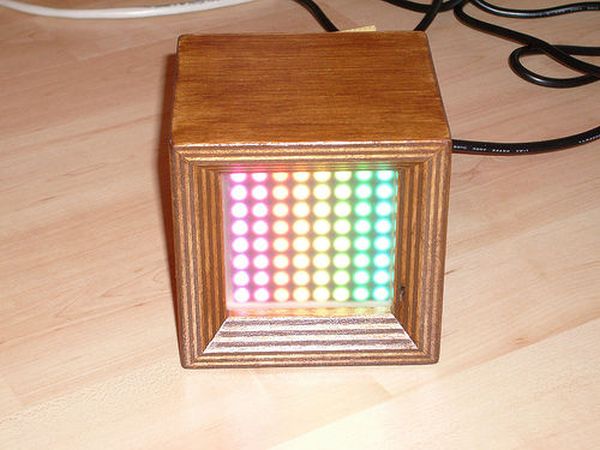
Image (1) illustrates the working principle of the PWM algorithm. Say the code is given a value of 7 for the brightness of LED(0,0). Furthermore it knows there is a maximum of N steps in brightness. The code runs N loops for all possible levels of brightness and all necessary loops to service every single LED in all rows. In case the loop counter x in the brightness loop is smaller than 7, the LED is turned on. If it’s larger than 7, the LED is turned off. Doing this very quickly for all LEDs, brightness levels and base colors (RGB), each LED can be individually adjusted to show the desired color.
Measurements with an oscilloscope have show that the display refresh code takes about 50% CPU time. The rest can be used to do serial communication with a PC, read buttons, talk to an RFID reader, send I2C data to other modules…
Step 2: Talking to shift registers and LEDs
A shift register is a device that allows for loading data serially and a parallel output. The opposite operation is also possible with the appropriate chip.
There’s a good tutorial on shift registers on the arduino website.
The LEDs are driven by 8-bit shift registers of the type 74HC595. Each port can source or sink about 25mA of current. The total current per chip sinked or sourced should not exceed 70mA. These chips are extremely cheap, so don’t pay more than about 40cents per piece. As LEDs have an exponential current/voltage characteristic, there need to be current limiting resistors.
Using Ohm’s law:
R = ( V – Vf ) / I
R = limiting resistor, V = 5V, Vf = LED’s forward voltage, I = desired current
Red LEDs have a forward voltage of about 1.8V, blue and green range from 2.5V to 3.5V. Use a simple multimeter to determine that.
For proper color reproduction one should take a few things into account: spectral sensitivity of the human eye (red/blue: bad, green: good), efficiency of the LED at a certain wavelength and current. In practice one simply takes 3 potentiometers and adjusts them until the LED shows proper white light. Of course the maximum LED current must not be exceeded. What’s also important here is that the shift register driving the rows must supply current to 3×8 LEDs, so better not push the current up too high. I was successful with limiting resistors of 270Ohm for all LEDs, but that depends on the make of the LED matrix of course.
The shift registers are interfaced with SPI serial. SPI = Serial Peripheral Interface ( Image (1) ).
Opposed to the serial ports on PCs (asynchronous, no clock signal), SPI needs a clock line (SRCLK). Then there’s a signal line telling the device when the data is valid (chip select / latch / RCLK). Finally there are two data lines, one is called MOSI (master out slave in), the other one is called MISO (master in slave out). SPI is used to interface integrated circuits, just like I2C. This project needs MOSI, SRCLK and RCLK. Additionally the enable line (G) is used as well.
An SPI cycle is started by pulling the RCLK line to LOW ( Image (2) ). The MCU sends its data on the MOSI line. The logical state of it is sampled by the shift register at the rising edge of the SRCLK line. The cycle is terminated by pulling the RCLK line back to HIGH. Now the data is available at the outputs.
Step 3: Schematic
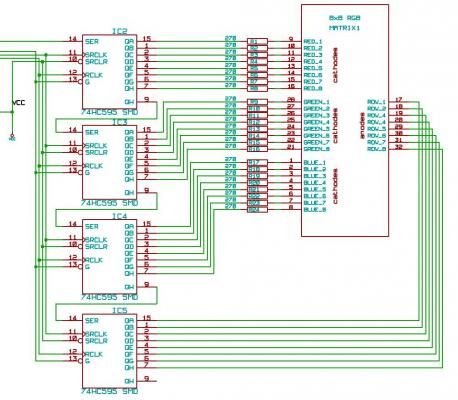
Image (2) shows the rest of the schematic with the MCU, connectors, quartz…The attached PDF file contains the whole works, best for printing.
 v303_schematic.pdf(765×539) 189 KB
Step 4: C++ Source code
void do_something(void);
int main(void) {
do_something();
}
void do_something(void) {
/* comment */
}
The Arduino IDE does not require this step, as functions prototypes are generated automatically. Therefore function prototypes won’t show up in the code shown here.
Image (1): setup() function
Image (2): spi_transfer() function using hardware SPI of the ATmega168 chip (runs faster)
Image (3): framebuffer code using a timer1 overflow interrupt.
Pieces of code that have a slightly cryptic look for beginners e.g. while(!(SPSR & (1<<SPIF))) {} use the MCU’s registers directly. This example in words: “while the the SPIF-bit in register SPSR is not set do nothing”.
I just want to emphasize that for standard projects it is really not necessary to deal with these things so closely related to hardware. Beginners should not be frightened by this.
 V3_x_boards_test_v3.pde.zip
LED’s
For more detail: 64 pixel RGB LED Display – Another Arduino Clone
-
How is color mixing achieved on the display?
Pulse width modulation is used to turn power ON and OFF quickly, adjusting brightness levels to create the full spectrum of colors. -
What type of shift registers are used to drive the LEDs?
The project uses 8-bit wide shift registers of the type 74HC595 which can source or sink about 25mA of current per port. -
How does the system handle multiple tasks simultaneously?
A framebuffer held in RAM is parsed by an interrupt routine in the background, allowing the user to communicate with a PC or read buttons while the display updates. -
What is the CPU time consumption for the display refresh code?
Measurements show that the display refresh code takes about 50% of the CPU time, leaving the rest for other operations. -
How are current limiting resistors determined for the LEDs?
Resistors are calculated using Ohm's law based on the supply voltage, the LED's forward voltage, and the desired current. -
Which protocol is used to interface the shift registers with the MCU?
The Serial Peripheral Interface (SPI) protocol is used, requiring MOSI, SRCLK, and RCLK lines. -
How many loops run for the brightness calculation?
The code runs N loops corresponding to the maximum brightness steps for all necessary rows to service every single LED.