Summary of 4x4x4 RGB LED Cube
This article explains building a 4x4x4 RGB LED cube controlled by an Arduino using shift registers for pin expansion, including mechanical assembly, wiring, circuit design, and software multiplexing with BAM for 4-bit color brightness. It covers creating LED planes, connecting anodes and cathode layers, using 74595 shift registers and transistors for layer multiplexing, and driving the cube via SPI and timer interrupts for animations.
Parts used in the 4x4x4 RGB LED Cube:
- 64 common cathode RGB LEDs
- Arduino board
- 7 x 74595 shift register ICs
- 2N2222 transistors (for multiplexing cathode layers)
- 22 ohm resistors (current limiting)
- Wires for anode and cathode connections
- Jig for LED alignment (wood or custom)
- Wooden piece or cardboard box (to mount cube)
- PCB or protoboard for control circuit
- SPI library (software component)

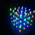
This article describes how to build a 4x4x4 RGB LED CUBE (Fig. 6) that is controlled by Arduino.
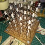
Cube construction
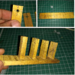
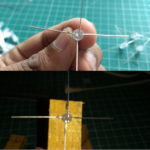
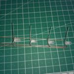
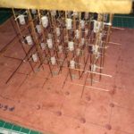
We need 64 common cathode RGB LEDs for our cube. Test all LEDs before soldering. Bend all the leads out 90 degrees apart as shown in fig.2. Now construct a jig as shown in fig. 1. Insert LEDs in to jig then solder all 4 red led anode leads then green and then blue. Slowly remove this pile from the jig. We need 16 pile like this(Fig. 3). After that, take four pile from this. Connect cathodes of the first row then second and so on. Create 4 planes like this. Next short first cathode rows of each plane then second and so on. As shown in fig. 4. Insert cube in a wooden piece or cardboard box. Solder wires on each anode legs: fig. 5.
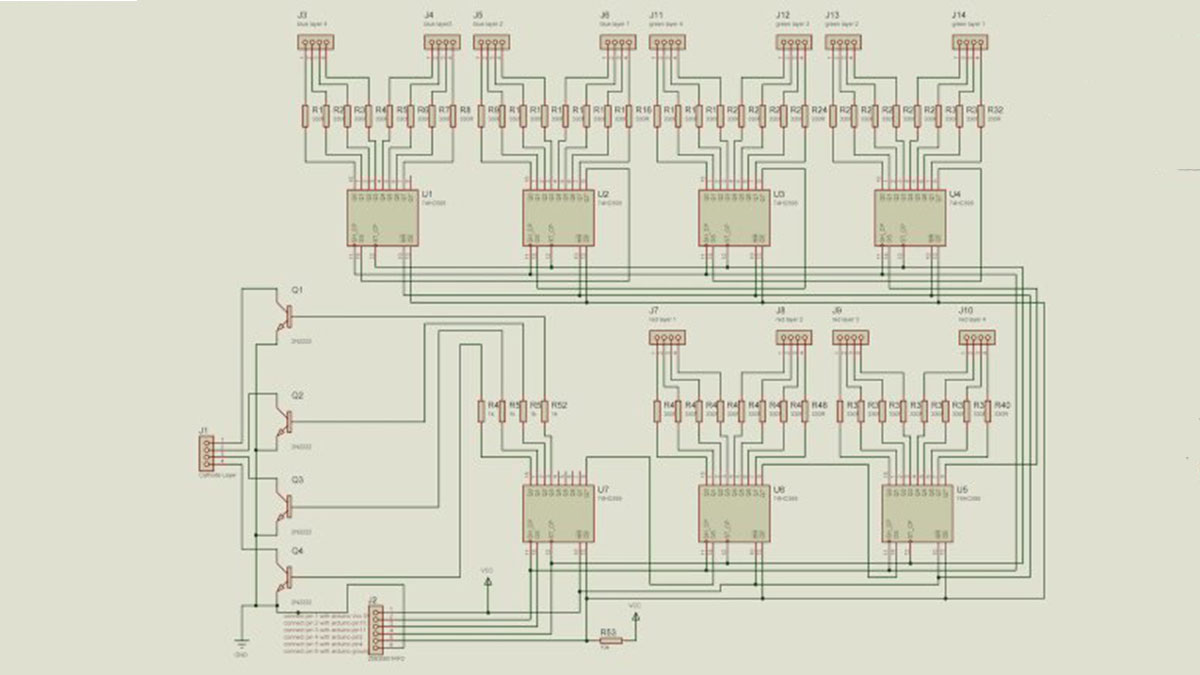
Circuit Diagram
Circuit diagram of RGB LED CUBE shown in fig:7. We have 64 LEDs in this cube and need to control each colour and each led individually. So for that, we need 64*3 pins, an Arduino board can’t do that alone. But this cube construction method will help us to control each led with shift registers. Now we need only 48+4 =52 pins for controlling 64*3 LEDs, for that we can use 7 shift registers each connected in series with Arduino. To Control each 48 LED column we can use 6nos of 74595 shift register ICs.IC 74595 is an 8-bit shift register. IC U7 is used for multiplexing 4 cathode layers with high current handling transistors (2n2222). 22ohm resistor is used for current limiting. Now let’s look at how led cube connect with our control board circuit. We have 4 vertical layers of red, green, blue LEDs. Connect first 4 bits of U6 with red layer 1 and second 4 bits with red layer 2.Connect first 4 bits of U5 with red layer 3 and second 4 bits with red layer 4.Connect green and blue also as in circuit diagram.
Program
First, we need to include the SPI library that’s what’s used to shift out data to shift registers. And then we define the latch pin and the blank pin which can be any digital pins you want those go out to the shift registers. The data and clock pins pin 11 and 13 are used by the SPI library and those are Hardware specific pins. We want to run the clock as fast as possible for the SPI so which the fastest it can be is to divide the system clock by 2, so 16 Meg divided by 2 now everything’s running it eight megahertz. We want to shift out 48+8 bit data at a time. I created a timer for multiplexing data. This timer interrupt will yank us out of the code every 124 microseconds. And this is our multiplexing frequency. It will update each cathode row data for every 124 microseconds. Here BAM technique used for controlling brightness. The brightness of the red green and blue component of that LED on a resolution base from 0 to 15 so it’s 4-bit resolution. By all of this data, I wrote a function to control all individual LEDs.With this function, you can write animations on your logic.
Download source code & schematics
Video Tutorial
Read More Detail :4x4x4 RGB LED Cube
- How many LEDs are required to build the cube?
The cube requires 64 common cathode RGB LEDs. - Can an Arduino control all LEDs directly?
No, an Arduino cannot provide 64 times 3 pins directly; shift registers are used to expand outputs. - What shift register is used to control the LED columns?
The 74595 8-bit shift register IC is used to control LED columns. - How many 74595 ICs are needed?
Six 74595 ICs are used to control the 48 LED columns and a seventh is used for layer control/multiplexing. - How are the cathode layers multiplexed?
Cathode layers are multiplexed using a 74595 output and high current handling transistors like 2N2222. - What resistor value is used for current limiting?
22 ohm resistors are used for current limiting. - Which Arduino pins are used for SPI data and clock?
Data and clock use hardware specific pins: digital 11 and 13 are used by the SPI library. - What multiplexing technique is used for brightness control?
BAM (binary angle modulation) is used for brightness control with 4-bit resolution per color (0 to 15). - How often is the multiplexing timer interrupt triggered?
The timer interrupt runs every 124 microseconds to update each cathode row. - How are the LED anodes connected during assembly?
Anodes are soldered in groups while LEDs are placed in a jig, creating 16 piles then assembled into planes with cathodes connected per row.