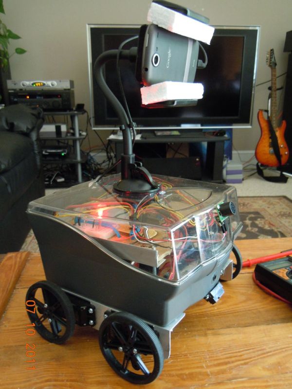
I started with an idea of what I wanted to do from the beginning but one attempt after another I finally got to where I am now. This robot can be remotely controlled from anywhere in the world and driven around the house. I can see through it’s eyes. Here is a brief run down. I’ll get into more later.
*I have taken a 3.5 floppy disk case as a body and added 4 servo’s converted to continuous operation for the locomotion.
*The hind brain if you will is an Arduino Uno Micro Controller with a sensor shield. This is used to listen to the sensors and drive the servo’s to make it move.
*I’m using a Android phone, specifically the Nexus One to act as the big brain which connects via wifi to my home network. It hosts a webpage which through it I can remotely control the bot and see what it sees through the phones camera. The software to do this comes from a project called Cellbots. The supporting site for them is cellbots.com. I’m using the android app named cellbots. Are you sensing a pattern here?
*I’m using bluetooth to connect the cell phone to the Arduino.
*I’m using voltage regulator to provide enough power to charge the phone and provide power for the servos.
*I’m powering it all from a 6.6 volt LiFePO4 Battery. That’s one of those new Lithium Iron batteries that will take alot of punishment.
*I’m recharging it using a Deltran 6 volt battery tender charger which I intend to set up for a automated charging station.
*I’m using a two router system port forward to the bot for the web page and a second router for all my home stuff to protect it.
While It’s not actually finished, I do have enough working to prove it works as a concept. I can remotely drive it around the house. There are alot of pieces of this puzzle that probably deserve their own Instructable and I have drawn from at least one other Instructable on this site that I’ll give credit to.
Step 1: Servo’s and the Arduino used to Calibrate
The arduino micro controller, model uno, is a pretty simple micro controller to use. I won’t get into how to program it but I will discuss a little bit about using it in this application.
The servos I used are EXI model B1226 sourced from:
http://www.hobbypartz.com/12exiseb1.html
You will need a servo ‘horn’ to connect them to a wheel of some sort. This servo requires a special horn made for the B1228 model.
http://www.hobbypartz.com/sehosetforap.html
The servo is technically not a continuous servo but so incredibly easy to convert. See pictures…
1. remove cover
2. remove baring, and two gears.
3. remove little white circular clip using your finger nails.
4. calibrate the potentiometer to make it spin the same speed in both directions and to stop when you send it the command to center itself.
5. use nail polish to glue Potentiameter into place.
6. reassemble all except the little white clip you removed with your finger nails.
Why use this specific servo?
1. Extremely high torque and just the right speed for 3 to 4 inch wheels running at 6 volts.
2. It’s $14 each.
3. It already has the stops removed that prevent it from rotating continuously.
4. To make it run continuously just remove the clip. Originally it was designed to turn 8.5 times from one end to the other. After you remove the clip it will run continuously.
5. so no cutting, no soldering. If you have the calibration program on your arduino you can have it done in under 5 minutes easy.
Source code to calibrate the servo is below. It rotates right for 3 second stays still for 15 seconds, left for 3 seconds, then still for 15 seconds. You rotate the potentiameter back and forth until the thing stops spinning during the 15 second periods for several cycles of the program…
#include
Servo myservoR;
void setup() {
Serial.begin(9600);
delay(5000);
Serial.println(‘Start’);
myservoR.attach(11);
}
void loop()
{
myservoR.write(180);
Serial.println(‘sending 180’);
delay(3000);
myservoR.write(90);
Serial.println(‘sending 90’);
delay(15000);
myservoR.write(0);
Serial.println(‘sending 0’);
delay(3000);
myservoR.write(90);
Serial.println(‘sending 90’);
delay(15000);
}
Step 2: Servo mounts and wheels
I used 1.5 inch x 1.5 inch L bracket from the local hardware store in my case it was Lowes. I used a hack saw to make 90 degree cuts and then pushed the area where the servo goes flat with my fingers (feel free to use tools).
The servo Horn gets pressed on and then the screw those through the enter to hold it on.
I then attach the wheels to the servo horn using screws.
The wheels are 80mm wheels from pololu.com
http://www.pololu.com/catalog/product/1430
Servos
For more detail: 4 Servo drive CellBot which can be remotely controlled using Arduino