
Summary of 3x3x3 LED Cube with Arduino Lib using arduino
This article details the construction of a 3x3x3 LED cube controlled by an Arduino. Unlike larger projects, this design uses minimal off-the-shelf components and includes a clear circuit diagram with a unique software approach for easier programming. The build involves creating a wooden jig to assemble LEDs into three levels and nine columns, soldering them together, and mounting the structure on a perfboard.
Parts used in the 3x3x3 LED Cube:
- 1 Perfboard
- 3 NPN Transistors (2N2222, 2N3904, BC547, etc.)
- 12 Resistors (~220 ohms and ~10k ohms)
- 13 Headers (male or female)
- 27 LEDs
- Wire
- Scrap wood for jig
- Drill
There are other Instructables about building LED cubes, this one is different for several reasons:
1. It’s built with a low number of off-the-shelf components and hooks up directly to the Arduino.
2. A clear, easy to reproduce circuit diagram is provided with plenty of photos.
3. A unique approach is used for the software which makes programming the cube easier and more expressive.
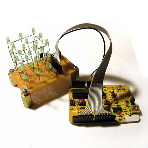
Parts needed:
– 1 Perfboard
– 3 NPN Transistors (2N2222, 2N3904, BC547, etc.)
– 12 Resistors (~220 ohms and ~10k ohms)
– 13 Headers (male or female)
– 27 LEDs
– Wire
Step 1: Prepare the LEDs
This step largely follows the LED Cube 4x4x4 but we’ll be building a 3x3x3 cube instead. A cube of this size is about as big as it gets without introducing additional circuitry and complexity. We’ll need a total of 27 LEDs that will be grouped into three sets of nine.
Each set of nine LEDs will share a common connection amongst their cathodes (negative leads). I’ll refer to each of these sets as a “level”. Each of the nine LEDs on a level is connected to the corresponding LED on the other two levels through their anodes (positive leads). These will be referred to as “columns”. If that didn’t make sense it will become self explanatory as we build the cube.
To start we’ll use a drill to create a jig out of a small piece of scrap wood. The jig will hold the LEDs in place while we solder them. I decided to space the holes around 5/8 of an inch apart (~15 mm) but the exact distance isn’t critical. The hole should have a tight fit around the LED since we don’t want them to move around while soldering.
Once the jig is done we’re going to bend the cathode of each LED in a 90 degree angle. The cathode is identifiable in three ways: 1) It’s the shorter leg, 2) It’s on the flat side of a round LED, 3) it’s connected to the larger piece inside the LED. Make sure you bend the cathode in the same direction for all of the LEDs.
Now we’re ready to begin soldering.
Step 2: Solder the LEDs
First place nine of the LEDs in your newly built jig. Position them so that the legs point in the same counter-clockwise direction. The photos show the cathode pointing clockwise with the anode facing out, but I’d turn the LEDs around if I did it again in order to keep the leg from obstructing the view of the LED.
Solder the sides together, one pair on each side. Use small clips to keep the legs clamped together while applying the solder.
Once each of the four sides are soldered, move the clips to hold the corners together and apply solder to each. Lastly, solder the cathode of the middle LED to one of the sides and trim away the excess.
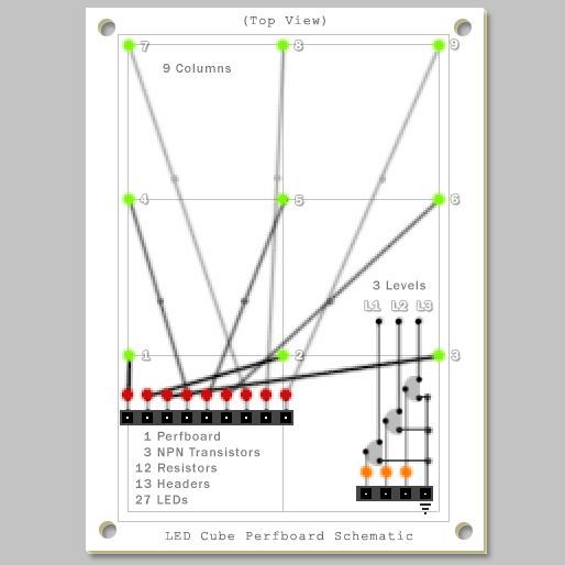
Repeat three times.
You should now have three sets of nine LEDs. Position two of the sets one on top of the other. Keep the distance equal to the spacing already established between LEDs. Once you’re comfortable with the spacing you can clamp each set of legs using two clips, one in each direction, to keep the legs firmly in place while soldering. You may need to bend around a LED to get a good connection. Solder each of the nine pairs, one at a time.
Do this one more time and you’re done with the cube.
Place the cube on one side of the the perfboard. Make sure the nine legs are positioned apart evenly while you guide each one through a hole. My board has five holes between each set of legs. You want to leave as much room as possible on the other end of the perfboard to fit the various components.
For more detail: 3x3x3 LED Cube with Arduino Lib
- How many LEDs are required for this project?
A total of 27 LEDs are needed, grouped into three sets of nine. - What is the size of the LED cube described?
The project builds a 3x3x3 cube, which is considered the maximum size without adding extra circuitry. - How should the LED legs be identified before bending?
The cathode is the shorter leg, located on the flat side of a round LED, or connected to the larger internal piece. - What tool is recommended to hold LEDs during soldering?
A drill is used to create a jig from scrap wood to hold the LEDs in place while soldering. - How are the LEDs connected within each level?
Each set of nine LEDs shares a common connection amongst their cathodes within a single level. - How are the levels connected to form columns?
The nine LEDs on one level connect to the corresponding LEDs on other levels through their anodes to form columns. - Can the hole spacing in the jig be exact?
No, the exact distance is not critical as long as the fit is tight enough to prevent movement. - Why is the perfboard positioned on one side of the cube?
This allows space on the other end of the board to fit the various electronic components.
