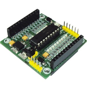
The PIC 18 PIN (DIP) Development / Evaluations Board demonstrates the capabilities of Microchip’s 8-bit microcontrollers, specifically, 18 Pin PIC16F1847. It can be used as a standalone demonstration board with a programmed part. With this board you can develop and prototype with all Microchip’s 18 PIN PIC microcontrollers. The board has a Reset switch and status LEDs. On board 3.3 V and 5V DC regulators allows using 3V and 5V PICs, This board support both 3.3V low power and normal 5V operation. All I/O Pins out with 2xfemale headers
Development Board Features:
- 16 I/O Ports
- Onboard 5V and 3.3V Supply
- 3.3V or 5V Supply selection by jumper
- Dual line I/O
- On board Power Indication
- On-board ICSP Port (PICKIT2 Standard Programming Port)
- Well labeled legends
- All outputs has provision for LEDs for output indication
- Replaceable PIC Microcontroller,
- Crystal and capacitor mounting under the PCB
PIC16F1847 Micro-Controller Specifications:
- Enhanced Mid-range Core with 49 Instruction, 16 Stack Levels
- Flash Program Memory with self read/write capability
- Internal 32MHz oscillator
- Integrated Capacitive mTouch Sensing Module
- Data Signal Modulator Module
- MI2C, SPI, EUSART w/auto baud
- 2 ECCP & 2 CCP (Enhanced/Capture Compare PWM)
- Comparators with selectable Voltage Reference
- 12 Channel 10b ADC with Voltage Reference
- 25mA Source/Sink current I/O
- Four 8-bit Timers (TMR0/TMR2/TMR4/TMR6)
- One 16-bit Timer (TMR1)
- Extended Watchdog Timer (EWDT)
- Enhanced Power-On/Off-Reset
- Brown-Out Reset (BOR)
- In Circuit Serial Programming (ICSP)
- On Board In-Circuit Debug
- Wide Operating Voltage (1.8V – 5.5V)
- Low Power PIC16LF182x/4x variants (1.8V – 3.6V)
- Standby Current (PIC16LF1847): 30 nA @ 1.8V, typical
- Program Memory Type Flash
- Program Memory (KB) 14
- CPU Speed (MIPS) 8
- RAM Bytes 1,024
- Data EEPROM (bytes) 256
- Digital Communication Peripherals 1-UART, 1-A/E/USART, 2-SPI, 2-I2C2-MSSP(SPI/I2C)
- Capture/Compare/PWM Peripherals 2 CCP, 2 ECCP
- Timers’ 4 x 8-bit, 1 x 16-bit
- ADC 12 ch, 10-bit
- Comparators 2
- Temperature Range (C) -40 to 125
- Operating Voltage Range (V)1.8 to 5.5
- Pin Count 18
- XLP Yes
- Cap Touch Channels 12
For More Details: 18 PIN PIC Development Board

