Summary of 12V NE555 PWM Controller
This article details the construction of a DIY 12V NE555 PWM controller, an alternative to purchasing a pre-made module. The author modified a standard circuit design to include a toggle switch, DC power socket, and screw terminals for enhanced usability. Beyond controlling DC motor speeds, the device functions as an LED dimmer, hot wire cutter heat controller, or electrolytic etcher voltage controller. All components were sourced affordably from eBay for approximately $2.90 AUD.
Parts used in the 12V NE555 PWM Controller:
- 0.01 uF ceramic capacitor
- 0.1 uF ceramic capacitor
- 2 x 1N4001 rectifier diodes
- 1 x 1N4004 rectifier diode
- IRF530 100 V 14 A TO-200AB MOSFET
- TO-220 heat sink
- 2 pin screw terminal
- DC Barrel Jack (female)
- 100 ohm resistor
- 1k ohm resistor
- SPDT toggle switch
- NE555 timer IC
- 8 pin DIL socket
- 100k ohm potentiometer
- 70 x 100 single sided PCB
- connection wire
While making my mini table saw I bought a 12 V motor speed controller module from eBay. Fair enough, I thought … that was an easier and straight forward solution. But then I decided to make my own.
I did some hunting around on the interweb and found a pretty good starting point in Circuits Today, but then, I needed to make some modification and tweaking of the circuit. I wanted to add in a toggle switch, a DC power socket and a 2 pin screw terminal into the design to make it easier to make and use.
There were some other minor alterations that I made to the design as I went, for convenience and to meet my specific needs.
I also want to point out that this circuit is not simply a motor speed controller, but a PWM controller. On the one hand, that means that it can do a lot more than just vary the speed of a DC motor. This circuit will output a 12 volt current with a varying duty cycle. It can be used as 12 V DC:
- Motor Speed Controller;
- LED Dimmer;
- Heat controller for a Polystyrene Hot Wire cutter;
- voltage controller for an electrolytic etcher; and
- etc.
The applications for this circuit are limited only by its 12 V DC nature. How you apply that is up to your imagination and experimentation. For instance, I’m thinking of using this circuit to make a vibrating platform for agitating my PCB production acid bath …
Parts you will need
All parts were purchased from eBay.
- 1 x 0.01 uF ceramic capacitor
- 1 x 0.1 uF ceramic capacitor
- 2 x 1N4001 rectifier diodes
- 1 x 1N4004 rectifier diodes
- 1 x IRF530 100 V 14 A TO-200AB MOSFET
- 1 x TO-220 heat sink
- 1 x 2 pin screw terminal
- 1 x DC Barrel Jack (female)
- 1 x 100 ohm resistor
- 1 x 1k ohm resistor
- 1 x SPDT toggle switch
- 1 x NE555 timer IC
- 1 x 8 pin DIL socket
- 1 x 100k ohm potentiometer
- 1 x 70 x 100 single sided PCB
- some connection wire
All of this cost me around $2.90 AUD
Step 1: The Circuit PDF
These PDF provide you with the printable circuit board for producing the NE555 PWM controller.
- C1 – 0.01 uF
- C2 – 0.1 uF
- D1 and D2 – 1N4001
- D3 – 1N4004
- R1 – 100 ohm
- R2 – 1K ohm
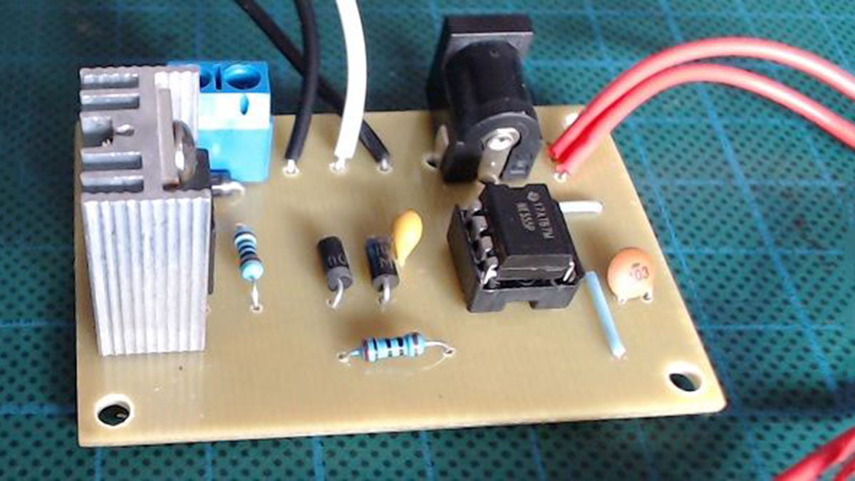
Take care with the orientation of the 555 timer and note the notch location. All other parts are pretty clearly indicated on the board.
There are 3 jumpers on the board. From GND to C1, from pin 7 of the 555 to D1 and from GND to the IRF530 Source pin.
The switch (top left) is not labelled in the PCB view, however, it is pretty straight forward. Also, there is a through hole below the IRF530, this is for the post of your heat sink.
Read more: 12V NE555 PWM Controller
- What is the primary function of this circuit?
This circuit is a PWM controller that outputs 12 volt current with a varying duty cycle. - Can this circuit be used as a motor speed controller?
Yes, it can vary the speed of a DC motor. - Does the circuit support applications other than motors?
Yes, it can be used as an LED dimmer, heat controller for a Polystyrene Hot Wire cutter, or voltage controller for an electrolytic etcher. - Where did the author purchase all the parts?
All parts were purchased from eBay. - What was the total cost of the project?
The total cost was around $2.90 AUD. - How many jumpers are required on the PCB?
There are 3 jumpers on the board connecting GND to C1, pin 7 of the 555 to D1, and GND to the IRF530 Source pin. - What specific modifications did the author make to the original design?
The author added a toggle switch, a DC power socket, and a 2 pin screw terminal to the design. - Is there a specific orientation requirement for the 555 timer?
Yes, users must take care with the orientation of the 555 timer and note the notch location.