Sometimes I just have those days where I really want to make something neat with the Arduino I have lying around, but I know I don’t have the patience for a more involved project that’ll take more than a day or so. This is for one of those days.
The premise is as follows:
A random color is shown on an RGB LED for a few seconds, then extinguished. You, the player, then press and hold a button to cycle through the colors and release when you see that color come up. If you’re close, it flashes green. If you’re not, it flashes red. You can then use the Arduino’s reset button (or, as I will show you how, another button wired up to do the same) to reset the sketch and start a new game.
This is a relatively simple project that only uses parts you probably already have lying around in your “random components” box, and if not, they’ll run you less than $10 at RadioShack if you already have an Arduino.
Step 1: Step 1: Gather your materials
You will need:
(1) Arduino microcontroller (I used an Uno, but really any Arduino will do as long as it has 3 PWM pins and an available RESET pin)
(1) Common-Cathode RGB LED (All the elements connected to one common negative lead)
(2) Normally-open momentary pushbutton switches (only one is pictured – the second is for if you want to hook up an external Reset, which is optional.)
(2) 10 KOhm resistors (Brown-Black-Orange)
(3) 1 KOhm resistors (Brown-Black-Red)
The resistor values don’t matter as much here, but it is important that if you substitute different resistors for the 1KOhm resistors that they are the SAME. I chose my resistors based mainly on what I had on hand, and with the values here the current through each LED element is limited to about 4mA, with a peak current draw (out of the microcontroller) of about 13mA if every element is on and both buttons are held down.
Step 2: Step 2: Prototype the Circuit
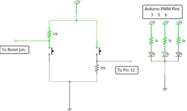
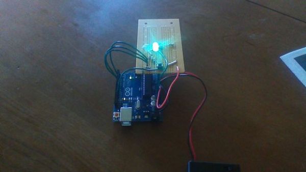
I always think it’s a good idea to prototype the circuit on a breadboard before soldering it together on perfboard. This allows you get a feel for the circuit’s operation and how it fits together before you solder it permanently. A circuit diagram is attached to this step.
Be sure to take note of which leads on the RGB LED correspond to which elements, and be careful NOT to connect it backwards! In the picture of the LED attached to this step, mine go Red-Cathode-Green-Blue.
It’s important to remember the 1K series resistors for each element in the RGB LED, or else your operation will be erratic. This is because each separate element has a different forward voltage (The voltage required to light the element if nominal current is flowing – i.e., the “voltage drop” across the element), and Red is generally the lowest, around 2.2 volts with Green and Blue between about 2.2-2.8 volts for a typical LED. When constructing an array of identical LEDs powered by the same source, it is okay to have only one resistor connected to the common lead of the entire array, since the forward voltage of each LED is the same. When powering different LEDs with the same power supply, however, you must attach series resistors to each to minimize the differences in the forward voltages. If you forget these resistors, or only connect one common one, the elements can flicker and red will often overpower the other two.
Also, note the way the switches are set up. The Reset circuit of the Arduino is triggered when the reset pin is pulled LOW (digital 0, or analog 0 Volts), and so it it connected to 5V through a pull-up resistor (Wikipedia) to “pull” the voltage to 5V (HIGH, digital 1, 5V) when the switch is open. When the switch is closed, the reset pin is grounded and the Arduino resets the sketch.
The other switch (the “game” switch) is set up similarly, but instead uses a pull-down resistor to keep the input LOW until the switch is pressed, at which point it is connected to 5V and pulled HIGH. It is set up in the code that the input triggers when pulled HIGH, but it’s just as simple to trigger it on LOW and set it up identically to the Reset pin. Arduino inputs are digital, which means they respond to values that are either HIGH or LOW, but not in between. This is why it is important to connect your switches to inputs such that they are either connected to 5V or ground, but never left floating. A floating (unconnected) input can cause erratic operation as it flips back and forth due to some ambient electric field.
In both cases, once the switches are pressed, both resistors limit the current flowing from 5V to ground. It’s useful to choose large values for these resistors, so this current draw is small.
Step 3: Step 3: Program your Arduino
I have attached the program I used to this step. It was made in IDE Version 1.0.5. Upload it like you normally would any Arduino program. Make sure everything is connected right and let ‘er rip! Feel free to modify the code in any way you like, just tell me, so I can use it myself! Better code = better projects = better people.
For more detail: 1 LED Game with Arduino Uno and an RGB LED