
Summary of 0-10V Voltage Monitor
This article describes a 0-10V Voltage Monitor project centered on the LM3914 IC. It visually indicates voltage levels using ten LEDs, powered by a 12V DC supply. The device offers two display modes—Bar and Dot—which can be selected via a jumper setting. Designed as an affordable and low-current consumption tool, it features header pins for connections and four mounting holes on a compact PCB.
Parts used in the 0-10V Voltage Monitor:
- LM3914 IC
- 10 Light Emitting Diodes (LEDs)
- Jumper J1
- Header pins for power and voltage connection
- PCB board
0-10V_Monitor_PIC
This project is a 0-10V Voltage Monitor.
Description
0-10V Volt monitor project has been designed around LM3914 IC, It is an easy and less expensive project which instantly visualizes voltage level. The project is based on the popular LM3194 IC from Texas instruments. Handy 0-10V DC Voltmeter can be used as a voltage tester.
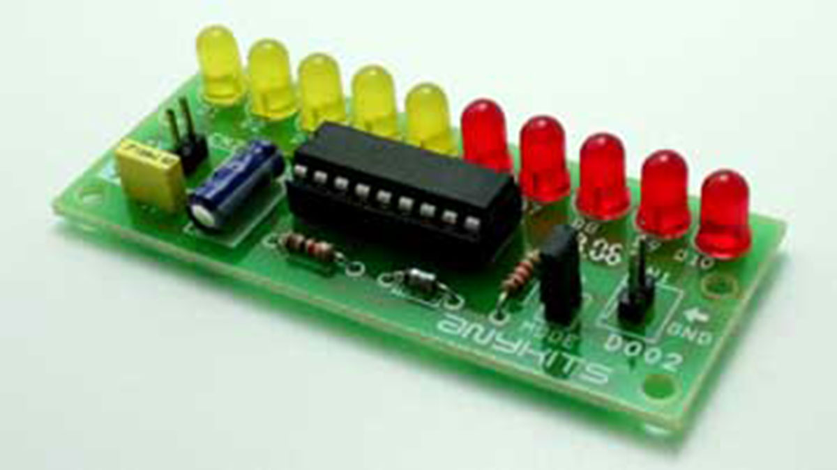
The LM3914 senses the voltage level at the input pin and drives the 10 light emitting diodes based on the voltage detected on input connector. Circuit works on 12V DC. J1 Jumper is used to select the DOT mode or bar graph mode.
Specifications
Input: 12 VDC @ 100 mA
Output: 10 LED’s
2 Types of display – Bar and Dot selectable by a jumper
Very low current consumption, typical 100mA
Header pins for connection of power and voltage in
Four mounting holes of 3.2 mm each
PCB dimensions 31 mm x 74 mm
Connections
CN1 connections: VCC &GND: 0-10V variable input voltage supply
CN2 connections: VCC &GND 12VDC power supply
J1 (Jumper): Open: Dot Mode & Close: Bar Mode
For more Details: 0-10V Voltage Monitor
- What is the main function of this project?
The project instantly visualizes voltage levels. - How does the circuit indicate the detected voltage?
It drives ten light emitting diodes based on the input voltage. - Can I select between different display modes?
Yes, you can choose between Bar and Dot modes using jumper J1. - Does the project operate on AC or DC power?
The circuit works on 12V DC. - What is the typical current consumption of the device?
The typical current consumption is 100mA. - How do I set the display to Bar Mode?
You must close the Jumper J1 to enable Bar Mode. - What are the dimensions of the PCB used?
The PCB dimensions are 31 mm x 74 mm. - How many mounting holes are provided on the board?
There are four mounting holes of 3.2 mm each.
