Summary of ΙoΤ – Automatic Router (and Server) Reset
This article details a DIY automatic reset system for an Atom-based NAS and ADSL router that frequently freeze. The creator used a NodeMCU (ESP8266) to ping the devices and trigger relays for cold restarts when connectivity is lost, eliminating the need for manual basement visits. The project combines hardware components like relays and LEDs with custom Arduino IDE software to monitor network status and control power cycles automatically.
Parts used in the Automatic Router and Server Reset Project:
- NodeMCU board (or Wemos D1 mini)
- Songle 5V relays (plain or complete board)
- NPN transistors (e.g., N2222)
- Resistors (600Ω and 300Ω)
- Diodes (e.g., 1N4001)
- LEDs (Red, Green, Yellow)
- Nokia 5V cell phone charger (350mA)
- Female and male connectors
- Small plastic electric box
- Silicone gun
Usually inventions are invented to serve a need or to solve a problem. So this small gadget that i constructed came to serve a need of mine.I have a NAS, Atom based file server, that runs on Ubuntu, but from time to time the operating system freezes and i have to cold restart it. The problem is that the server is at the basement and it is very inconvenient to go there and restart it. Also the ADSL router sits beside the server and sometimes also freezes, usually, in the summer time, where temperatures of 40+ Celsius occur in my hometown Athens Greece. The previous year i was playing with a nodemcu board based on an ESP8266 chip and i was very impressed of what this little device could do. I was wondering if could solve both of my problems and i started experimenting with the software and the hardware i needed to create the solution.
In the process i dealt with many problems and i will try to share everything because i am sure that some of you will benefit and use this knowledge to solve your problems and create interesting instructables.
Step 1: Explanation of the Problem, Manual Solution and Thinking
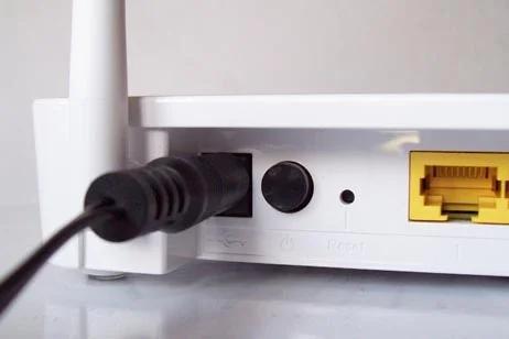
To solve the problem manually i just removed the power supply from the server as it didn’t respond to any command and the same with the router. But as i previously say this is not convenient and sometimes the problem occurred when i wasn’t at home so no one else knew what to do.
So the problem could be solved if instead of the server or router one wire of the power cable was connected to a power relay in Normally Close (NC) and Common (C) position. So normally the power flows to the device (server or router). Also i didn’t want to cut the cables so i had to use female and male connectors. Of course i needed a device to check if the devices are alive and then decide to cold restart them or not.
Nodemcu is the perfect candidate for the control device. It is cheap, it can connect to the network, it can check if the router is connected to the internet and it can ping the server. After that it can decide to cold restart or sleep.
Step 2: Hardware
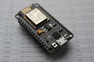
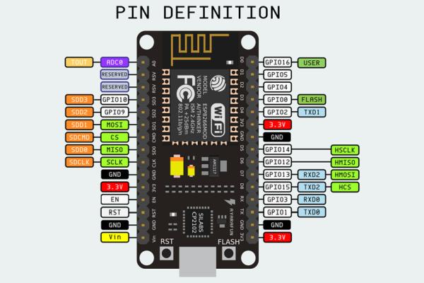
1. First of all i used a nodemcu that i was testing for sometime, but you can buy one cheap from ebay for about 3€. Information about NodeMCU. Some prefer to use Wemos D1 mini. It is a little smaller but it has practically the same capabilities. As you can see in the schematic it has many digital input and output pins and we are very lucky that it can programmed using the arduino IDE after we add the ESP8266 library. You can view what other platforms are supported by arduino IDE here
2. I have used plain songle 5V relays but you can buy the complete board that has everything you need onboard to use the relays (you can also view the video). Plain relays cost 0.3€ or less each and the complete board 1.5€ for a double relay. In case you buy the plain relays you are going to need two NPN transistors (ex. N2222), two 600Ω resistors and two diodes (ex 1N4001). Of course if you want to reset more or less devices you have to adjust accordingly.
3. I have used three led to display power (red), device OK (green) and device not OK (KO, yellow). For the red led i have used a 600Ω resistor in series to limit its luminosity and 300Ω for the green and the yellow. Red led is connected directly to VCC (5V) , green and yellow are connected to GPIO ports of nodemcu that are supplying maximun volatge of 3.3V
4. For powering the nodemcu i used an old NOKIA 5V cell phone charger (350mA).
Step 3: Heat the Solder Iron
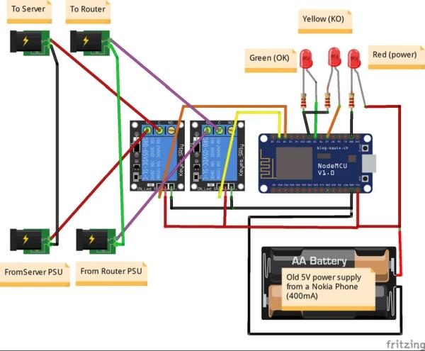
In the two images you can view the connections. I also embedded the fritzing files if someone wants to study the circuit in more detail. The connections using the relay board are simpler. In this case connect D1 and D2 to IN1 and IN2 of the relay board. If you are asking whether you can use other ports instead of D1 and D2 my answer is NO because from my test these are the only safe ports that will not trigger relays in case of resetting or cold rebooting of NodeMCU ( i learnt this in the hard way). You can read a discussion here.
If you want to do it in the hard way (and learn more) you can do the connections as on the second image (to be more explaining only one relay is pictured). As stated in the songle relay datasheet, it needs around 90mA to work, so we cannot connect it directly to GPIO ports of the NodeMCU. We are going to power it up directly from the 5V Nokia power supply using a transistor as a switch. Try not to forget that transistors are not switches. They just act as switches (another lesson that i learnt in the hard way). So you have to connect the load (the relay in our case) with on pin to 5V and the other pin to the Collector of the NPN transistor and ground the Emitter. The Base should be connected to D1 (or D2) with a resistor to protect the transistor. I have used a 600Ω resistor which permits (3.3V-0.7V)/600Ω = 4mA BE current and tested that the relay works when triggered from the GPIO. The diode is connected inverted to the poles of the relay and used as a fly back diode to protect the relay of spiking currents when it switches of. If you omit it then when the transistor turns the CE connection off, the magnetic energy stored inside the inductor coil of the relay has nowhere to go and it can damage the circuit with a static spark. With this diode the circuit is closing and the energy flows through the inductor coil relay until is completely turned to heat (clever, ha!)
Step 4: The Software
Inside the zip file there is the main .ino program with explanation of almost everything and a parameters.h file that you have to adjust to your network and needs.
There is a misunderstanding between GPIO number ports and digital numbering on the breadboard of NodeMCU. To overcome the problem in the beginning of the sketch there are definitions that will make everything easier.
#define D0 16
#define D1 5 // I2C Bus SCL (clock)
#define D2 4 // I2C Bus SDA (data)
#define D3 0
#define D4 2 // Same as “LED_BUILTIN”, but inverted logic
#define D5 14 // SPI Bus SCK (clock)
#define D6 12 // SPI Bus MISO
#define D7 13 // SPI Bus MOSI
#define D8 15 // SPI Bus SS (CS)
#define D9 3 // RX0 (Serial console)
#define D10 1 // TX0 (Serial console)
You just have to connect the nodemcu to your computer select board NodeMCU (my version is 1.0 i think) and then upload the code.
If you want, you can study and debug it from the serial communications port.
Also in case that you cannot find the esp8266 ping library it is here.
I have found the basic program in github and i must say it is an excellent job. You can find the original version here. Many credits to the original great maker.
Step 5: Assembly of the Final Product
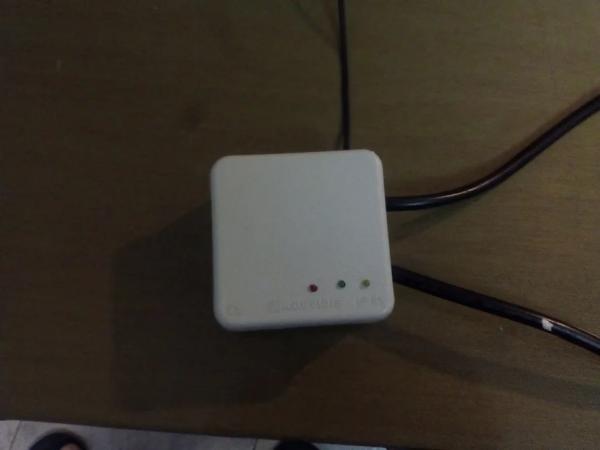
Assembly was made in a small plastic electric box that i found in a large retail store here in Greece and it cost 0.65€. I opened holes at the sides to connect the power supply inputs and cables and smaller holes for the leds and the 5V DC cable from charger. I have used silicone gun to glue everything inside.
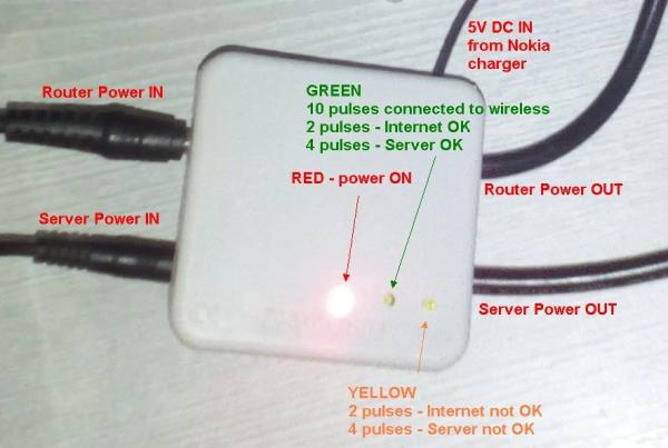
Led are programmed to display signals every 15 minutes or so but you can change the behavior in the parameters.h file.
Red is power ON.
Green displays OK (2 pulses for Internet and 4 pulses for Server).
Yellow displays not OK (2 pulses for Internet and 4 pulses for Server).
Some final thoughts.
I was thinking of using Solid State Relays instead of Electro Mechanical Relays to avoid the hassle using transistors, resistors and fly back diodes. SSR relays can be driven directly from GPIO because they can operate with smaller currents than EMR relays. But they cost a lot and the main disadvantage (from what i studied) is that they have to be powered to close the circuit (i haven’t found one with Normally Closed pin). If i am wrong please comment and i will edit.
Thank you for viewing and happy making.
Source: ΙoΤ – Automatic Router (and Server) Reset
- How can I solve the problem of inconveniently restarting a frozen server?
Connect one wire of the power cable to a power relay in Normally Close position controlled by a NodeMCU to automate cold restarts. - What device is suitable to check if servers are alive and decide on a restart?
A NodeMCU based on the ESP8266 chip is perfect as it connects to the network, pings the server, and controls the relay. - Which GPIO ports should be used to connect the relays on the NodeMCU?
You must use D1 and D2 because other ports may trigger relays unintentionally during a NodeMCU reset or cold reboot. - Can I use solid state relays instead of electro mechanical relays?
You can, but they cost more and usually require power to close the circuit, making it difficult to find a Normally Closed version. - What is the function of the flyback diode in this circuit?
The diode protects the circuit from spiking currents generated by the magnetic energy in the relay coil when the transistor switches off. - How do the LEDs indicate the status of the internet and server?
Green displays OK with two pulses for Internet and four for Server, while yellow displays not OK with the same pulse pattern. - Do I need to cut the power cables to install the relay?
No, you can use female and male connectors to avoid cutting the cables. - Where can I find the code for this project?
The main .ino program and parameters.h file are included in a zip file provided with the project instructions.