
Summary of Updating the Arduino Garage Door Circuit for the new Gliderol Garage Controller.
This article details the creation of an Arduino-based garage door interface for a Gliderol GTS controller. The project replaces a previous BOSS BOL6 setup by implementing three relays to control start, stop, and down functions. It also incorporates two magnetic switches to monitor the door's position via rail sensors. Due to enclosure constraints, a generic case was modified with drilled holes and secured using 3mm nylon screws. The circuit connects to switches and terminals using color-coded RCA connectors (Red, Black, Green, Blue), with an additional relay board stacked on top of the Arduino.
Parts used in the Arduino Garage Door Interface:
- Arduino
- Gliderol GTS garage door controller
- Three relays
- Two magnetic switches
- Generic enclosure
- 3mm nylon screws
- Additional board with relays
- RCA connectors (Red, Black, Green, Blue)
We moved house recently and I was obviously very keen to continue the home automation routine. As described in Adventures with an Arduino – Part 1: The Business Problem, I created an Arduino based garage door interface to integrate with a BOSS BOL6 garage door controller. The new house however uses a Gliderol GTS controller – and this one has up, down and stop buttons.
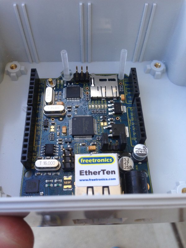 I created an updated circuit with three relays, one for each of the start, stop and down actions. I’ve also included two magnetic switches attached to the rail to determine the position of the door (open, closed, in between).
I couldn’t get a standard Arduino enclosure that would hold this circuit, so I ended up buying a generic one and then drilling/filing the appropriate holes in the enclosure.
I purchased some 3mm nylon screws to mount the circuit within the enclosure. An additional board with the relays etc is then slotted into the top of the Arduino board (although not depicted below).
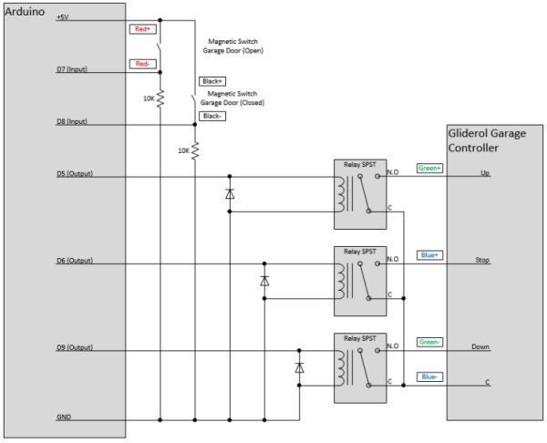 I decided to use RCA connectors for the connections to the switches and controller terminals. I used Red, Black, Green and Blue – and the connectors are depicted in the above circuit diagram.
For more detail: Updating the Arduino Garage Door Circuit for the new Gliderol Garage Controller.
- Why was the original Arduino garage door interface updated?
The update was necessary because the new house uses a Gliderol GTS controller instead of the previous BOSS BOL6. - How does the new circuit control the garage door actions?
The circuit uses three separate relays to manage the start, stop, and down actions required by the Gliderol GTS controller. - What components are used to determine the door position?
Two magnetic switches attached to the rail are used to detect if the door is open, closed, or in between. - Why was a generic enclosure chosen over a standard one?
A standard Arduino enclosure could not hold the updated circuit, so a generic one was purchased and modified. - How was the circuit mounted inside the enclosure?
The circuit was mounted using 3mm nylon screws after drilling and filing holes in the generic enclosure. - What type of connectors were used for the wiring?
RCA connectors were used for connections to the switches and controller terminals. - Which colors were assigned to the RCA connectors?
The connectors used were Red, Black, Green, and Blue. - How is the additional relay board connected to the Arduino?
An additional board containing the relays is slotted into the top of the Arduino board.
