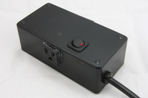
If you have ever wanted to control high voltages/currents with an Arduino, setup up a complicated light timer, or even have Siri turn on a Lamp. Then this is an instructable for you! In this instructable in a few simple steps we will build a self-powered smart relay (Arduino style) power box. This box will allow you to safely switch high voltages/currents and since it contains an Arduino compatible board you can program it as you see fit, or even connect it to SiriProxy. Then you just plug it in, and off it goes! Now let’s build it.
Materials Needed:
Project Box – similar to a 6x2x3, (http://www.radioshack.com/product/index.jsp?productId=2062282)
Smart Relay Board – http://www.sparkyswidgets.com/Products/Store/Details/tabid/81/ProductID/1/Default.aspx
BlueSmirf – bluetooth module http://www.sparkfun.com/products/582
Power switch – Similar to this will work fine (http://www.radioshack.com/product/index.jsp?productId=3118987)
Replacement power cord – something like this from Lowes, HD, Ace (http://tinyurl.com/72n7yqe)
Cable strain relief – Mouser part# 836-1200(http://tinyurl.com/7tlpkaw)
Snap in power plug(x4) – Mouser part# 693-4300.0703(http://tinyurl.com/7pb57h8)
transformer – pretty much any will work as long as it can supply enough for the relays (http://www.radioshack.com/product/index.jsp?productId=2102494)
diodes(x4) – 1n4004, any recitifing diode should work (the 1n400x line is good for the application, http://tinyurl.com/6qen2pg)
capacitor – 220uF electrolytic cap jsut to help keep things clean on the DC output side of the transformer Mouser part# 667-ECA-1HM221(http://tinyurl.com/7ylc8al)
extra wire(14awg) – this can be from the power cord just cut an extra bit off, (we need some for Neutral, Hot, and Ground)
Heat shrink – If you can get color coded great, if not your average Radioshack black stuff will work fine
Crimp connectors – Your standard automotive style crimp connectors for 14awg(male and female, blue colored ones)
Tools Needed:
Drill
3/32 drill bit
9/16 drill bit
Dremel – we’ll use this to clean up our rough opening for the sockets and switch
Screwdrivers – a set of tech type screwdrivers should do fine(standard and philips)
Pliers/Wire Cutters – the strain relief can be difficult to push in, pliers make this much easier
Soldering Iron – A decent soldering iron with some good solder
Some better super glue than I used 🙂
Our main steps:
1)Build small unregulated power supply(the relay board has regulators)
2)Prepare enclosure(cut openings, pre fit switch and sockets, mount power cord)
3)Initial wiring of mains wires, wire to switch, preparation of unions, test switch and Vout of transformer
4)final wiring, soldering of union joints, heat shrinking, wiring of lv relay board power
5)wifi/bt/xbee module, then close it up and test it out
Step 1: Build DC Power Supply
The basic steps to build this DC power supply are:
1)Create the bridge rectifier – Using the 4 diodes we will create the rectifier that will turn the AC current into DC and supply us with a fairly steady DC positive Voltage. Images 2,4,5 depict the layout and components needed for this portion. Notice the direction of the diodes and how half of the rectifier is tucked under the transformer. Placement of this portion should allow the transformer to sit on top of it and expose the positive half(as shown in main image). this allows for easy connection of the transformer secondary to our rectifier and help save some space(image 7). You can use the diode leads to make the rectifiers connection on the bottom side of the board(image 8)
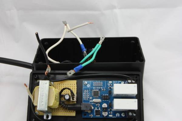
2)Mount transformer- mount the transformer above the rectifier making sure the SECONDARY is on the rectifier side, solder the tabs on the under side to hold the transformer in place. now is a good timer to wire the secondary to the rectifier. And you can even add a couple short pieces of the 14/16awg wire on the PRIMARY side, we will need these later to wire the switch,sockets,relays.
3)Place Capacitor- Place the capacitor and use its leads to wire into the positive and negative rails (the long lead is + on the cap), then solder it into place.
4)make the final connections to the negative(ground) and positive rails of the rectifier (here we used a 3 pin connector but you can hard wire a DC power plug, or even straight to the relay board input).