No longer will you have to pay hundreds of dollars for a heart rate monitor! The Smart Heart Monitor will be able to do all of your cardiac measuring needs for you!
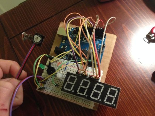
The Smart Heart Monitor measures the user’s heartbeat using an LED and a very sensitive photo-resistor attached to the user’s ear. A light will blink to the user’s heartbeat, and the program will calculate the user’s beats per minute. The BPM will be displayed on a 7 segment display. If the user’s BPM exceeds a user-set limit using a potentiometer, an alarm will sound. Once the user’s BPM lowers below that limit, the alarm will turn off.
Step 1: Step 1: Materials
You will need the follwing materials for this project.
One Arduino UNO
One breadboard
One 5V Pulse Sensor that can be bought at the pulsesensor website.
One 4 digit 7 segment display (12 pins)
One potentiometer
One LED
One piezoelectric speaker
Depending on how efficient you are with your cable management, around 30 breadboard cables
Step 2: Step 2: Assembly
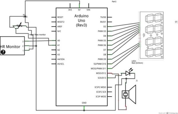
This step is the hardest, so make sure you follow along closely! The circuit diagram attached may be helpful if you get stuck.
1.) Connect the LED to digital pin 13, and then to ground.
2.) Connect the piezoelectric speaker to digital pin 12, and then to ground.
3.) Connect the potentiometer to the 5V and ground it, and attach the output to analog pin 2 (I was having difficulties on my board with analog pin 1)
4.) Connect the pulsesensor heart rate monitor. Red wire goes to 5V, black wire is grounded, and the purple wire should go to analog pin 0.
5.) Wiring up the 4 digit 7 segment display. (This part is the most confusing, so I’ve split it up into smaller steps. Refer to the picture with the 7 segment display in it for help. Also, if you are having troubles connecting all of your wires, check out how I wired mine with the white wires.)
b.) connect pin 2 to digital pin 5
c.) skip over pin 3
d.) connect pin 4 to digital pin 4
e.) connect pin 5 to digital pin 8
f.) connect pin 6 to digital pin 11
g.) connect pin 7 to digital pin 3
h.) connect pin 8 to digital pin 10
i.) connect pin 9 to digital pin 9
j.) connect pin 10 to digital pin 7
k.) connect pin 11 to digital pin 2
l.) skip over pin 12
All done with the circuitry! Time for the code.
For more detail: Smart Heart Monitor