Persistence of Vision (POV) Wands are a fun way to create interesting long exposure photographs and light displays. The wand consists of a single row of LEDs controlled by an Arduino Uno. When the wand is turned on it appears to be flickering in a random pattern, but if you move it quickly back and forth, you will see text or an image appear. This wand project is incredibly customizable, I’ve included all CAD files, firmware, build documentation, and schematics. Feel free to choose your own color LEDs, write personalized messages, and maybe even add something new to the project!

(1x) Arduino Uno REV 3 Radioshack #276-128
(20x) Amber Super-bright LED Indicator Radioshack #55050630
(1x) Arduino Proto Shield Radioshack #276-140
(1x) 9V Alkaline Battery Radioshack #23-866
(1x) Heavy-Duty 9V Snap Connectors Radioshack #270-324
(20x) 1/4 watt resistors (sample calculation below)
from the specs of the LEDs I used:
“Continuous forward current: 25mA”
“Forward voltage: 3V”
using the following relationship:
V(volts) = I(amps) * R(ohms)
rearranged to:
R = V / I
we can calculate the resistance as follows:
voltage across resistor = 5V – 3V = 2V
2V / 0.025A = 80ohms
I used 100 ohm resistors so that the LEDs wouldn’t be operating at their maximum ratings. Check the datasheet of the LEDs you use to calculate these values.
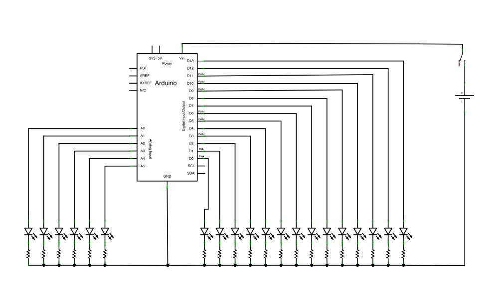
I’ve attaching a fritzing document with a breadboard and schematic view of the circuit (and included them above) for reference.
Step 1: Build a support for your wand
The first thing you’ll want to do is make a mount for your project. I laser cut a piece of acrylic into a wand shape, but you could use a piece of plywood, cardboard, or plastic. I’ve attached the adobe illustrator and eps files of the wand and correct hole 0.1″ hole spacing for the LEDs and resistors; even if you don’t have a laser cutter, these files still might be useful to print out as a template. Drill out the holes with a drill and a small drill bit. The rectangular holes at the bottom of the wand will be used for mounting a 9 volt battery.
Step 2: Add resistors
Thread the leads of all 20 resistors through their holes on the wand mount.
Step 3: Solder resistors
Each resistor is connected to an LED on one side and ground on the other. Bend one of the leads of each resistor so that they are touching each other and solder them all together in a row. Clip the excess metal from the leads. Leave the last lead unclipped so that it can be attached to a wire later.
Step 4: Add header pins to protoboard
Solder header pins to the pins connections on the arduino protoboard. Make sure you are soldering them on the correct side! For best results I recommend soldering the first and last pins first (as in figure 3), then check to see if the pins are straight and flat on the board (figure 4). If they need to be adjusted it will be much easier with only two pins soldered down. Once everything is lined up, solder the middle pins (figure 5).
Step 5: Attach toggle switch
Solder the toggle switch onto the middle of the arduino proto-shield as shown in the images above. Solder a jumper wire between the side lead of the switch and the Vin pin on the proto-shield.
Step 6: Attach battery connections
Solder the red lead of the battery connector to the middle pin of the switch. Solder the black lead of the battery connector to the ground pin of the protoshield.
(20x) Amber Super-bright LED Indicator Radioshack #55050630
(1x) Arduino Proto Shield Radioshack #276-140
(1x) 9V Alkaline Battery Radioshack #23-866
(1x) Heavy-Duty 9V Snap Connectors Radioshack #270-324
(20x) 1/4 watt resistors (sample calculation below)
For more detail: Persistence of Vision Wand using Arduino