Andrew O’Malley, an amazingly creative maker, created this fanstastic Open Source Arduino-based clock that can display the time in many different ways: if not enough, one can also add his own personal animation.
Compared to other clocks based on Arduino, this one has two distinctive features: a single board with the ATmega 328P chip plus the RTC (not a shield) and a led matrix display (16 x 24 pixels) based on Holtek HT1632 chip. The display is already mounted and with a serial interface.
Due to this hardware solution, in which the specialized chips help the Arduino board (tacking care of the complexities of managing a matrix display and monitoring the time), you would think of just few lines of code. It would indeed be so if Andrew O’Malley had not chosen to create a design object: from a simple time display to an opensource system capable of displaying complex animations.
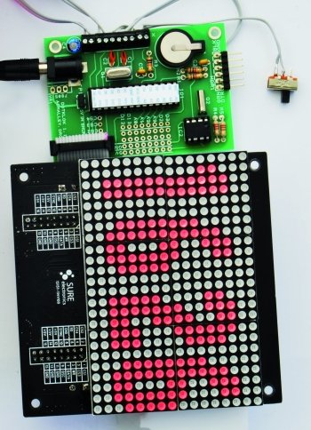
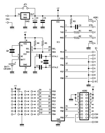
The current hardware version (the 1.1) is published under Creative Commons Attribution-Sharealike (CC BY-SA 3.0) license. This version uses a 28-pin DIL version of the ATmega 328P, the real-time clock from Dallas Semiconductor DS1307, an optional 7805 voltage regulator and two quartzs. The first is 16 MHz and is for the microcontroller; the second is the typical cylindrical quartz for watches, gives 32.768 kHz.
A few other passive components complete the circuit. The lithium backup battery is connected to pin 3 (VBAT) of the RTC.
The power supply of the microcontroller and the display is 5V: with all the LEDs on the display reaches about 200 mA absorption, while the microcontroller takes just a few tens milliamperes. Looking at the scheme, one can see that the typical Arduino pin mapping has been reported on the various connectors following a compatibility logic.
The serial port is connected to pin 2 (RXD) and 3 (TXD) of the microcontroller. The DTR serial port connects to pin 1 (RESET) in order to activate the bootloader when you start programming. The circuit only sports the TTL interface so to connect to a PC to use the Arduino IDE one must use the classic USB / Serial interface. The schema includes a header (HDR1) realized with a 6-pin strip to connect to this interface.
The second connector (HDR2) is instead chosen specifically (16 pins in two rows) to be compatible to that of the LEDs matrix; on this connector we have the connection of the pins D9, D10 and D11 (corresponding to 15, 16 and 17 on the micro) used for communication with the HT1632 chip. D11 (Pin 17) is connected to CS1, D10 (Pin 16) is the Write Clock, while the D9 (Pin 15) is the Data.
From these pins you can guess that the serial communication is comparable to two wires SPI. Indeed, the support library, as we’ll see in software section, uses this mode of communication. You can see how four different chip select (CS) are possible to cascade up to four modules for a total matrix of 16 x 96 pixels.
The X1 connector connects pin from D8 to D4 (14, 13, 12, 11 and 6 of the micro) to a screw terminal block alternating with the pins of the micro and the grund: here we will connect the four buttons normally open and the diverter to manage the various operating modes of the Dotklok.
The small breadboard that is provided on the circuit corresponds to the wiring diagram in a series of pitches that connect to the pin at the bottom left of IC1. On an Arduino board these correspond to pins A0, A1, A2, A3, D2, D3, D12 and D13. This is a good amount of pins (both digital and analog) with which to invent new expansions and functional enhancements to Dotklok.
IC2 (the RTC DS1307) is interfaced to the micro with the classic I2C connection on pins 27 and 28 – SDA and SCL lines for the micro – that are for this type of communication on the Arduino UNO. This choice allows us to use libraries already available to interface the RTC without having to make major changes.
Interestingly to see, how it is possible, with this information about the correspondences of the various pins with the Arduino pins, to realize the Dotklok prototype without changing the software: using a some jumpers and a breadboard it is possible to take an Arduino UNO, add the Dallas chip, the display (see on our shop), the few passive components and the buttons to obtain the same result.
Support libraries
Before analyzing the sketch structure, it’s worth taking a look at the libraries that Andrew O’Malley has decided to use to make it all easier.
The program starts with this series of includes
#include <Wire.h>
#include <RTClib.h>
#include <Button.h>
#include “ht1632.h”
The first library is present in the basic Arduino IDE installation and serves to manage the I2C protocol used by the real-time clock. In addition to communication, the RTC also needs the support library that makes it more intuitive the reading and writing of the date and time or the reprogramming of stored data.
The Button library is a rather interesting solution, written by Alexander Brevig, to manage buttons of all sort.
Thanks to this library you obtain an abstraction from the hardware: the reading of a button, is simply defined by the pin to which it is connected: all goes with easy to understand functions (IsPressed, stateChanged, wasPressed etc..). The library allows you to create multiple instances for the various buttons. In our case the buttons are named from b1 to b5.
The last library was written to manage the HT1632 controller through high-level instructions that exploit all the various functions. In the library folder you only find the file with the various define relative to controls, while all the management is developed in an example sketch, that Andrew took to make the Dotklok. This example sketch implements all the necessary functions to handle the activation commands for one of the four chips that can be cascade connected, and then those for the brightness or to write directly the bytes in the memory. In addition, the example library supports both the ignition of individual pixels with a plot instruction, and the copying of characters in specific location of the screen. All the components needed to easily manage a graphic panel.
For more detail: An Open Source, hackable Digital Clock