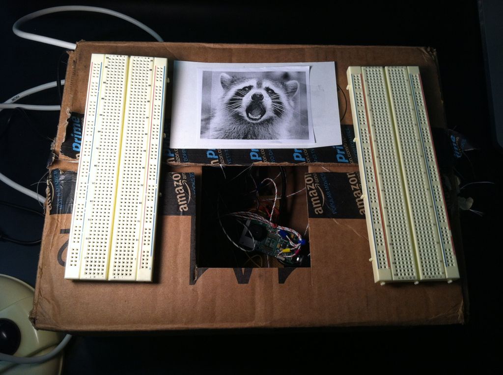
Welcome to my instructable on how to make an Arduino-controlled motion sensing camera and alarm!
The motivation behind this project, which I worked on in my electronics class at Pomona College, was the need to keep away varmints (particularly raccoons) that were digging up my parents’ yard. Although a simple motion sensing alarm would probably do the trick, I decided to add a camera to the circuit so that I could actually capture the critters in action! I have yet to field test the device, but the results so far are promising.
One really great thing about this project is that it builds upon the work of several other cool instructables:
· Hacking A Keychain Digital Camera for Arduino Control by smb
http://www.instructables.com/id/Hacking-A-Keychai…
· Cat Repelling PIR motion sensor (covert) speaker box alarm by briannaw
http://www.instructables.com/id/Cat-Repelling-PIR…
· PIR Alarm Motion Sensor (with Encasing) by chuck4747
http://www.instructables.com/id/PIR-Alarm-Arduino…
So without further ado, let’s build it!
Step 1: Supplies and Tools
1) An Arduino uno (http://arduino.cc/en/Main/arduinoBoardUno)
2) Arduino software (http://arduino.cc/en/Main/Software)
3) standard usb cable for your Arduino to communicate with the software
4) A 9V battery with an adapter (http://playground.arduino.cc/Learning/9VBatteryAdapter)
5) Digital Concepts “Key Chain” digital camera (costs about $5.50). Can order them from Amazon at http://www.amazon.com/Digital-Concepts-Key-Chain-…
o IMPORTANT: you will need the software installation disk that comes with the camera so that you can install PhoTags express, which allows you to upload your images to a PC (note that you must have Windows 2000/MEXP/Vista 32-bit).
6) Passive infrared sensor (PIR). There are a variety of sensors out there so feel free to choose the one that suits you. For your convenience, I have listed two common models that are compatible with this instructable:
o Here is a datasheet for a sensor very similar to the one I used. The output prong is located between the positive and negative/ground, just like the sensor I used. https://www.futurlec.com/PIR_Module.shtml
o Another model can be found at Sparkfun (https://www.sparkfun.com/products/8630). Note that the negative/ground prong for this model is in between the positive and output (called “alarm” in the datasheet).
7) A super bright white LED. I used http://www.mpja.com/8mm-Super-Bright-White-100000… but there are plenty to be found on Sparkfun as well.
8) One other LED of your choosing. I used this to trouble-shoot my prototype and did not include it in my finished product.
9) A small piezo buzzer (https://www.sparkfun.com/products/7950)
10) One AA battery (1.5V) and battery holder. I strongly recommend a single battery holder. You can order one from Mouser Electronics (here are the results for a search I performed: http://www.mouser.com/Power/Battery-Holders-Clips-…
o If you use a multi-battery holder instead, make sure that you can easily solder an extra wire or two to one of the sockets (Step 4 shows exactly what you need to solder). Battery holders with external solder tabs are ideal.
11) Two relays. I used 8-pin dual in-line package (DIP) relays. A really great example is provided here: http://www.alliedelec.com/search/productdetail.as…
o the configuration of the relay will depend on the model, so be sure to reference your relay’s data sheet to understand how it should be wired up. If you don’t know how relays work, I highly recommend you check out this instructable: http://www.instructables.com/id/How-Electronic-Sw…
o If you’re stuck without a datasheet (like I was), there is a simple way to determine how to hook your relays up (which is explained later in this instructable).
12) two DIP 14-pin or 16-pin sockets (https://www.sparkfun.com/products/7939). I used 16 pin sockets but you’ll only need 14 for your 8-pin DIP relays.
13) One 56 ohm resistor (for use with the 8mm super bright white LED; be sure to check your LED’s typical/continuous forward current and forward voltage so you can calculate the ideal resistance for yourself!)
14) One 10K pull-up resistor (for your PIR sensor)
15) At least 4 arduino stack-able header pins (https://www.sparkfun.com/products/7937) . You’ll need two 6 pin and two 8 pin sockets. I say at least because if you make a mistake during the final soldering process, you’ll need backups.
16) 1-2 additional stack-able header pins for your PIR sensor, to place your sensor on your circuit board. These are not required if wires are already attached to the input-ground-output prongs (such as https://www.sparkfun.com/products/8630).
17) Proto-board (for finished product)
18) Optional, but incredibly helpful: breadboard for testing out your circuit before soldering
19) Jumper wire kit (https://www.sparkfun.com/products/124)
20) A few feet of insulated wire, ideally in several colors
21) Wire connectors (you may need them if your battery holder does not have solder tabs; see Step 4 for details)
22) Plastic ties to keep soldered wires in place
23) Optional: electrical tape in several colors (depends on how many colors of insulated wire you have)
Tools
· tiny Philips-head and flat-head screw drivers
· wire cutter and wire strippers
· two multimeters
· soldering iron and solder
· solder stand (makes life much easier if you don’t have an extra pair of hands to help you)
Step 2: Taking Apart the Keychain Digital Camera
This step is based on step 2 of smb’s instructable at
http://www.instructables.com/id/Hacking-A-Keychain…
I took most of my pictures after throwing away the parts I didn’t need, so while the pictures above are helpful (especially once you’re looking at the camera’s circuit board), I recommend you check out smb’s photographed instructions to fill in the gaps as you dissect your camera.
First, you will need to open up the battery compartment at the bottom of the camera to remove the AAA battery (it should be in there if your camera is new). Once the battery has been removed, you’ll need to use a flat-headed screwdriver to pry open the front cover of the camera (as demonstrated in the aforementioned instructable). Like the author of that instructable, I found it easiest to dig under the bottom-right portion first. The cover is a bit stubborn, but with a little persistence you’ll get it open in no time.
Once the cover is open, you will see a screw near the bottom, below the LCD display. Use your Philips screwdriver to unscrew it. Once you have done this, return to the camera’s battery compartment to remove the tape (you may have to scratch away some of it with one of your screwdrivers). Once the tape is removed, you will be able to open both halves of the camera (which the screw and tape had been holding together).
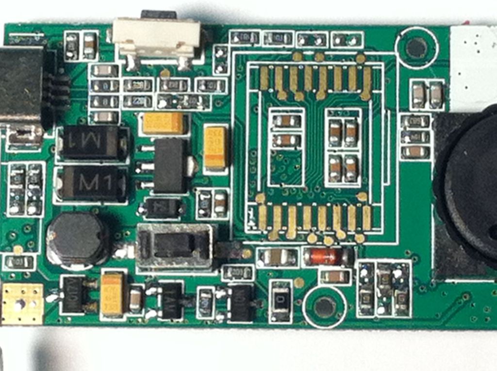
My first picture demonstrates what both halves of the camera should look like with all the components attached, minus a screw or too (Unlike the camera in smb’s instructable, my camera only needed one screw since its positive battery holder was soldered). Unscrew the remaining screw from the top left/center part of the circuit board (see fourth image), and from the positive battery compartment if present.
With all the screws removed, you should be able to remove your circuit board from the camera frame. Don’t panic if some pieces fall out! The “on” button, shutter button, viewfinder and LCD display will probably come off. This is perfectly fine because you won’t be using any of them again. One other piece that may become detached is the circular metal piece (labeled in the first image). Although it will not fall off (it is wired into the circuit board), it may detach from the foam tape. If this happens, you may want to apply a fresh layer of double-sided tape to secure the piece. This circular piece seems to generate the “beep” that you hear whenever you press the power button or shutter, because once the piece became detached, my camera stopped beeping, even after I reattached the piece with new foam tape. The beep is certainly not necessary, but you don’t want a loose piece getting in your way, especially since you will need to solder some wires to the circuit board.
Two other pieces that may break away from repeated handling are the positive and negative ends of the batter holder. If you plan on keeping the camera frame in your final product, you’ll need these pieces and will have to solder them back on if they fall off. However, if you choose to abandon the frame (as I did), you will have to remove the positive and negative ends of the camera holder, so if they fall out, you’re ahead of the game!
Step 3: Soldering Prep
This step can be tricky, especially if you have not soldered before (there are some good soldering instructables out there if you are new to soldering). The reason for this is that the four connections that you will be soldering to are fairly small and close to other conducting parts of the circuit. Thus, to prevent short-circuiting your camera, you will need to be extra careful not to let the solder leak into other conducting parts of the circuit board. On the bright side, there are only four connections you need to solder, so if you’re nervous, just take a deep breath. Now, let’s get to it!
It may take a while for your soldering iron to warm up, so go ahead and turn it on before reading further.
For more detail: Motion Sensing Digital Camera & Alarm using Arduino