A few years ago I saw an Instructable where Groover had used a pair of DVD-RW drives to make a pocket laser engraver. Inspired by the idea, driven by the recent purchase of a full-sized 50 watt CO2 laser cutter, and roused by the launch of the Microcontroller contest I took the decision to have a crack at making my own mini laser engraver.
 I have called the project the MicroSlice.
What are the features of the MicroSlice?
- The MicroSlice has a work area of 50mm x 50mm (2″ x 2″).
- It can cut paper and engrave wood & plastic.
- Open Hardware.
- Uses the Arduino UNO R3.
- All the software used by the MicroSlice, including the graphics program, is Open Source, and free to use!
- There is a 300mw 635nm Red Laser Diode, like you’d find inside a DVD-RW drive, which does the cutting & engraving.
- It comes as a kit to build at home, at a Hackspace, or with your local Maker group.
- There are 97 Laser-Cut parts in the kit!
- It will work with your Raspberry Pi.
The MicroSlice made the Grand Prize in the 2013 RadioShack Microcontroller Contest!
Massive thanks to everyone who voted, and of course to Radioshack for the super prizes 🙂
Step 1: To Begin
The basis for Groover’s axis was the two mini stepper motors from the DVD-RW drives. The motors drive the DVD head mechanism which either moved the laser cutting head, or the cutting table. My first starting point was to find a similar set of motors, and a reclaimed laser diode.
However I wanted a slightly different design. Where Groover has the cutting table move on the Y Axis, I wanted a fixed cutting table. To do this I took my inspiration from a gantry crane.
As the cutting table would be fixed, the cutting head must move along the Y Axis instead, but it must also accommodate the X Axis. So the whole cutting head, and the X Axis, must move along the Y Axis. Like a gantry crane moves up and down the dockside.
So I need two stepper motors with threaded shafts. The longer the shaft the larger the potential work-area for the cutting head. I’d also need a pair or runners for the Y Axis gantry to move along.
To cut a long story short I couldn’t find what I wanted from the DVD-RW drives I found. The stepper motors had no threaded bolts which could move along the threaded shafts and the laser diodes were firmly pressed into their housings that I was unable to remove them from the DVD-RW without causing damage. So in the end I turned to old faithful eBay to find the parts.
1 x Arduino UNO R3
1 x X Axis Motor
1 x Y Axis Motor
1 x Dual Relay
2 x Easydriver
2 x 5v LDO
1 x 3.3V LDO
2 x Heat-Sinks
1 x 45x45x10 Fan (12v)
4 x Stop Switches
9 x Magnets
4 x Rubber Feet
5 x Thumb Screws
1 x Laser Diode
1 x Laser Module
1 x Laser Driver
1 x Laser Lens
1 x 4mm Aluminium Tube
2 x 3mm x 150mm Steel Rod
1 x 3mm x 100mm Steel Rod
17 x M3 Microbarbs
6 x M2 Countersunk (6mm)
6 x M2 Nuts
6 x M2 Pan-head (6mm)
8 x M2 Pan-head (8mm)
4 x M3 Nylon Screws (6mm)
4 x M3 50mm Standoffs
7 x M3 Cap-Head Screw (8mm)
8 x M3 3mm Nylon Spacers
97 x Laser-cut parts!
The Microslice parts have been arranged to be laser cut out of two 3mm x 400mm x 300mm sheets of plywood or acrylic. The MicroSlice plans are attached as a zip file below. A pre-cut set of either Plywood or Acrylic laser parts are available fromThe LittleBox Company.
The MicroSlice uses a 300mw 635nm Laser Diode. It will hurt you if you are not careful. Please take care when handling the laser. Do not look at the beam, do not point it at yourself or anyone else. Do not be an idiot.
Step 2: The First Steps
Where do we start? Well firstly we need to establish a datum; a point at which all other measurements are made. I’ll be using the X Axis motor’s range of motion, the distance between each end of the stepper motor’s shaft, as our datum. I have picked this as we’ll need to position the middle of the range inline with the centre of the cutting table. From there we can measure the location of the three bolts holes for the stepper motor, and we’ll also be able to set a height above the cutting table.
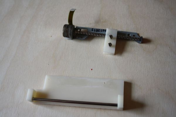
The motor comes fixed to a backing plate which will be removed and disposed of. The gantry must have several features; it must be able to have the X Axis motor attached to it, it must provide a cross-bar to steady the slider, somewhere for the laser module, and it must also have runners for the Y Axis.
As I’ll be cutting the parts from 3mm plywood I’ll be using vector graphics to design the parts. There are several programs available to help you with this part. Inkscapeis an Open Source vector graphics editor, it works on several platforms including Linux and the Raspberry Pi.
The gantry is to run along two 3mm x 150mm ground steel rods. There will be two sections of 4mm aluminum tube pressed inside the gantry which the rods fit down. The steel rods will take the weight of the assembly meaning that the motors only have to handle position changes and don’t have to battle the weight.
There are a total of ten different revisions of the gantry, with the tenth being part of the final build. To begin I kept it simple; mount the motor, get the correct heigh above the cutting table, and make sure it was wide enough to manage the full length of the X Axis.
Each new iteration of the gantry added something new, or corrected an error, or was most often the case it did both; improve, and add to the design.
Version 1 : Added the motor, set the height & width.
Version 2 : Reduced weight with cut-outs.
Version 3 : Corrections.
Version 4 : Increased the depth of the lower cross-bar from 15mm to 30mm to increase stability. The weight of the laser module was causing the gantry to tip forward and bind on the runners.
Version 5 : Added space & boltholes for the X Axis end-stops.
Version 6 : Corrections.
Version 7 : Added space & boltholes for the Y Axis end-stops.
Version 8 : Cut-outs made to the lower cross member allowing clearance for the Y Axis stepper motor.
Version 9 : Added brackets for the cables. This was used in the first dry-run of the MicroSlice.
Version 10 : Corrections made. Final version.
Step 3: Gantry Platform
The gantry platform had to serve two main purposes; support the runners for the gantry, and mount the Y Axis motor. The design constraints were limited to the width of the gantry, and to the length of travel of the Y Axis. I wanted a lightweight platform for the gantry, I also needed to fit the cutting table.
Step 4: The Cutting Table
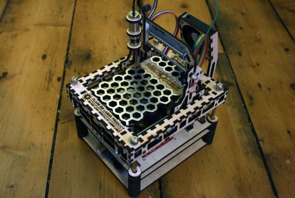
Everyone loves a honeycomb cutting table on their laser cutter, and I though the MicroSlice should have one.
For extra strength I used two layers of 3mm sheet glued together. There are two teeth at each end which interlock with two sockets on the Gantry Platform preventing the cutting table from moving.
I’ve pressed some neodymium magnets into the cutting table to help keep any paper secure while engraving / cutting. The area exposed to the laser has been covered with thick aluminium foil. This will protect the table from the laser’s heat.
Step 5: Heat-Sinks
The heat-sinks for the two LDOs come from a single reclaimed BGA heat-sink.
1 | Remove the heat-sink from the old BGA.
2 | Add 2.54mm pins to the two LDOs.
3 | File down the pins on the underside of the PCB.
4 | Cut the heat-sink into strips. I measured the width of the LDOs and cut a strip along the line with the screw hole. We’ll later use the screw holes to mount the LDOs to the MicroSlice.
5 | Shorten the strip to match the LDO.
6 | Clean up the edges, and remove the black from the surface where the LDO will be attached.
7 | Glue the LDOs to the heat-sinks using thermally conductive adhesive.
8 | Allow the glue to set.
You could also use thermal adhesive tape to attach the LDOs.
I have since found a source for new heat-sinks, check the parts list at the beginning of this instructable.
For more detail: The MicroSlice | A tiny Arduino laser cutter