Always wanted to take total control of your electric appliances even without being at home? Well, thanks to this instructable you will be able to do that and much more.
Some friendly suggestions before starting:
- Electricity is very dangerous, read and follow the “DANGER:” advices written in this instructable.
- If you don’t have any experience in the field of electrics/electronics seek for supervision from a knowledgeable person, although the circuit it’s very simple If you don’t know why you are doing what it’s being explained the odds are if you make a mistake you won’t be able to notice it, leading to unpleasant consequences.
- NEVER EVER work on the circuit while it’s connected to the grid, also don’t do it with it connected to the arduino, some tin solders transmit small amounts of current that can damage it.
- A steady power supply is recommended if the relay will be on during long periods of time.
To build a plug to plug arduino based-controlled switch you will need the following materials:
-1x plug to plug with manual switch (we want our circuit to fit inside).
-1x 5V relay (that holds 240V and 10A, check the datasheet of the one I used here).
-1x 2N2222 (also called PN2222) transistor.
-1x IN4002 diode (I used a 4007, small variations are acceptable).
-1x 1000 to 500 Ohms resistor. (I used one of ~750Ω)
-1x Prototype board (1,5×2 inches should be enough).
-1Strip x Female pin header (just for convenience).
Total cost: ~$6.
And the following tools:
-Microcontroller (preferably an original Arduino® board, notice I’m using a cheap imitation).
-Tin solder.
-Multimeter.
-Thermofusible glue gun + some glue (epoxy would work even better)
Step 1: First build and test.
First we want to mount and test all the components just to make sure we don’t do a lot of work to end with a defective circuit, you can find some pieces of code at the step 6.
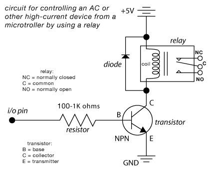
We can do this easily following the diagram shown above connecting the 5V to the 5V supply pin of the microcontroller and GND to the ground pin, i/o pin will be connected to the pin we want to use to send the signal, 10 in this case, and will have a resistance attached to it, the value might vary depending on the voltage used, mine works best with a 750Ω resistance, too high and it wont switch, too low and energy will be wasted.
To place the diode notice that they usually have a white band around the anode (the side of the “bar” if we talk about the symbol).
The reason for the diode and the transistor to be there is to protect your board, the diode redirects the voltage peak the coil induces to itself when the power supply is cut and the transistor acts as a protective shield for the board, so it can operate behind it without being affected by any harmful current variation, the resistor just limits the amount of current the base of the transistor can draw, making the circuit more efficient.
Connecting your microcontroller directly to the relay would end permanently damaging your chip.
IMPORTANT: If you want to make a “value=digitalread(button)” and then an “if(value==HIGH) {}” statement (just what I did) you’ll need to place a resistor in the order of some hundreds of thousands of Ohms from the pin the switch is placed to ground, that will avoid getting wrong results, and getting frustrated.
Once it’s all tested we can move on to the next step.
Step 2: Soldering it.
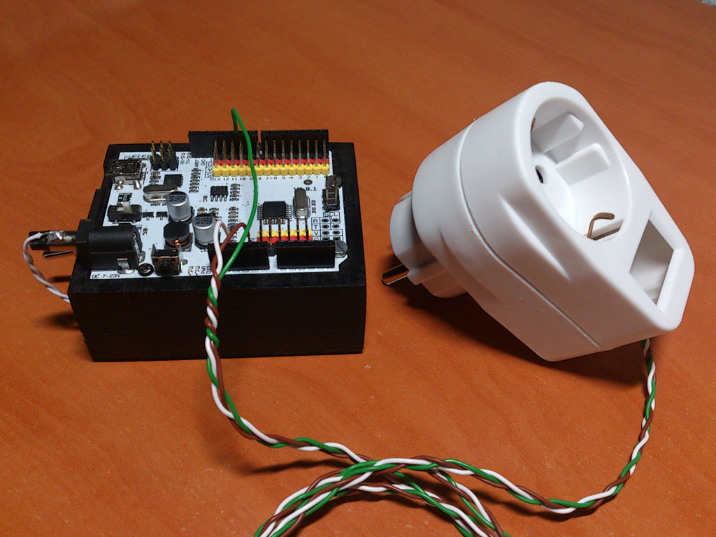
We begin by placing all the components in it’s place, you might find it’s quite difficult to insert the relay, that’s because the pins are not usually aligned with the board and the COM pin is also touching it, that’s why you see that little hole in the picture.
I have not added the resistance to the circuit because I wanted to experiment with more resistances, I ended placing it at the signal wire, I suggest you to place it directly on the definitive circuit just for convenience.
When you have managed to fit the relay in, place and secure the other components.
TIP: It’s useful to bend the legs of the components so they stay in place, also, if the relay is sturdily placed you can tape the transistor to it for a more even and easy soldering job.
Now we’re going to solder it permanently, I’ve uploaded pics of the final result so you can figure out how to connect it if you have some problems.
DANGER: I completely removed the cells of the board around the high voltage contacts (safety zone) with a sharp blade and some patience, I strongly recommend you to do the same to have a lower chance of having short circuits and to respect the standard spacing without making the circuit bigger, if you don’t remove the cells, you must space the components at least 2 cells in order to respect it.
No connections can be made inside the safety zone, which will have a radius bigger than 1,8mm over the naked board around the high voltage terminals.
If you can’t respect the safety radius, even by removing some cells, relocate again the components.
Please understand the importance of doing this.
You can also remove the useless cells before mounting the circuit by taping the cells you want to use and sanding them while the others are protected by the tape.
The “optional route” it’s useful if you’re going to use this circuit with low currents to make the cables stay at the right side and not below the board.
The “optional contact” is normally closed in most of the relays available, it is useful to use this contact when you are going to run devices for long periods of time only disconnecting them briefly, when connected to this contact, a HIGH output will mean the device is off while a LOW output will keep them on.
Step 3:
Once you’ve completed the circuit, test it again with the microcontroller, you should hear a “click” sound when the S pin gets 5 volts, if not check your circuit and code (The code I provided has been tested and guaranteed to work).
I recommend you to clean the space between the connectors (tin, residues…) with a brush or a piece of cloth and 96º alcohol.
At this point you can use your circuit to control small DC currents, such as 12-24V batteries.
Step 4: Plug modification.
Next we want to integrate the circuit inside our plug to plug switch, when we open it we must get rid of all what it’s not going to be used, in this case, the switch and a cable to power the light in it.
Notice that in the third picture the “base” for the switch has disappeared, I removed it with pliers and melting the plastic away to make room for my circuit, always trying not to damage the case.
I also made a small hole to pass the wires through when I mount the circuit.
When the switch and other useless things have been taken out cut and strip the brown cables to an optimal length to connect the circuit.
For more detail: Microcontrolled AC switch using arduino