Tested ExtraCore boards and kits are now available for sale from Rugged Circuits.
What is it?
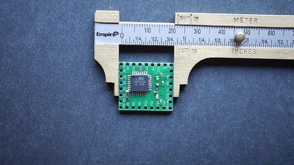
This Instructable will give you all the files and information you need to make your own Arduino Compatible in small surface mount package.
It requires a board manufactured to about 9mil precision. I recommend having the board manufactured at BatchPCB.com, Sunstone.com or your favorite board house.
We will be using a hot plate reflow method. It’s pretty easy and the components in this project tolerate the heat pretty well. I have not used a solder mask. Surface tension is your friend, but I did get some speckles on the boards and had to fix up one bridge. So feel free to make one if you know how. Solder masks won’t be covered here. Note: The fine commentators over at Hack A Day noted that you can actually do this project with a regular soldering iron using a method called “Tack and Drag.” So, if you don’t want to get a hot plate and solder paste, you have choices. That’s the magic of DIY.
Is this Instructable for you?
If you like Arduino and think you might like to learn how to do surface mount soldering, this is a great project to start with. If you don’t know about Arduino, you should get a development board and try it out. This isn’t a great beginner’s Arduino Compatible. It needs an external voltage regulator and it’s small form factor isn’t as friendly as the full sized boards. If you ever built a breadboard Arduino you will feel right at home here.
Can I modify this Instructable to do something custom?
You could make an Arduino with an on board compass, or on board robot controls. If you know how to make something work with Atmega328 you can move it on board with these files as a jumping off place.
What good is an Arduino anyway?
Just search Instructables for “Arduino”. This clone is really good for adding cores to existing projects or embedding in projects where space is at a premium.
What should I already know?
You should know your way around the Arduino IDE well enough to “burn the blink program” and have some practice wiring up an Arduino with simple circuits. It helps if you can already solder some. If you know how to make PCB’s or have ever build a “boarduino” you will be fine.
You will need the ability to open a command prompt in windows (or Linux), change directories and run programs as directed. The directions assume you are running Windows. If you run Linux I have faith you will figure it out.
Is this physically demanding at all?
You will need decent eye sight, a fair amount of hand eye co-ordination and good fine motor control. The griddle is also hot, so parts of this are sweaty work despite being physically easy
Open source goodies
The board is open source with a Creative Commons non-commercial license. You can get the eagle files from GitHub if you want to modify the board or use it as a jumping off point for your own clone.
https://github.com/dustinandrews/ExtraCore
Step 1: Tools you will need
Physical Tools
- Electric skillet or griddle
- Good ventilation
- Fine tweezers that are not even a little magnetized. Plastic is OK.
- Fine tweezers that can take 250 degrees F. Magetized is OK, clearly plastic is not.
- Magnifying glass. Depending on your eyes, higher magnification might be helpful.
- Solder paste
- Syringe or heavy duty zip top bag with a needle hole in the corner for applying paste
- Sewing needle
- Soldering Iron (Adjustable if at all possible)
- Fine solder wick
- Solderless breadboard and jumpers.
- 1-3 spare LEDs and 220-1k ohm resistors. (Tools since you can re-use them after this project)
- Any arduino compatible or ISP known to work with Atmega chips. These instructions assume an Arduino loaded with ArduinoISP
- A PC, these instructions assume windows. Linux will also work for sure.
- 5v FTDI breakout or cable or know how to do without.
Software
- WinAvr
- Arduino IDE
- Optiboot boot loader.
Note: You can use another bootloader if you wish, but you are on your own for burning the fuzes correctly. Messing up the fuzes can brick a chip, and the on board resonator will make it impossible to recover with even a high voltage programmer.
Step 2: Get the Circuit boards
You can now get a board with all the electronics from Rugged Circuits for $10.
If you want to have a circuit board made you have to DIY or send it to a “fab house.” These services require design files in a compatible format. “Gerber” is a common format that the Eagle software I used outputs and just about every board manufacturing service accepts.
The Gerber files I used are attached to this step. You can also get the Eagle Files from GitHub and make your own Gerber (or whatever) files if you need to modify the design. You can send the Gerbers to a fab house like BatchPCB or www.sunstone.com. I have used both. BatchPCB will cost about $13 not including shipping for one board and it will arrive in about a month. So far they have always sent me 2 boards when I ordered one, but I have had one board (of the two) have problems. Sunstone’s prototype service costs about twice as much and you will have boards in half the time. I quality of the Sunstone boards is good, but the silk screen isn’t as clear as BatchPCB with the same Gerber files. The price at Sunstone is the same for one or two boards so go ahead and get two.
If you want, you can order boards from BatchPCB via files I have already uploaded here.
(For the adventuresome an Untested version using 0805 sized components. Big thanks to RugedCircuits.com for help. You will need different parts than the ones listed in the next step as well and the layout is a little different.)
If you want to modify the design and make your own Gerber files, Spark Fun has a good tutorial and job file.
You can upload Gerbers to BatchPCB and have their DRC bot check them for free, Sometimes the design rules in Eagle show problems that you can ignore, but the “DRC bot” there rarely has false alarms.
There is also great, free online Gerber viewer here: http://circuitpeople.com/
Step 3: Gather Components
Surface Mount Parts
Here are the parts you need and the digeykey part numbers. For items that don’t have a minimum of 10, I recomend you get at least 2 and possibly more. If you have 2 good boards, you can make two Ardunio Compatibles. The small parts are really, really easy to lose so having extras is great. Be careful with them when you open the packages.
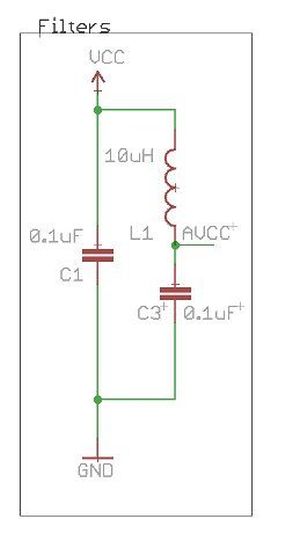
2x 445-6389-1-ND INDUCTOR MULTILAYER 10UH 0603
2x 490-1198-1-ND CER RESONATOR 16.0MHZ SMD
2x 754-1547-1-ND LED GREEN ROUND CLEAR SMD
2x ATMEGA328-AU-ND IC MCU AVR 32K FLASH 32TQFP
10x 541-10.0KSCT-ND RES 10.0K OHM .25W 1% 0603 SMD
10x 445-1316-1-ND CAP CER .10UF 25V X7R 10% 0603
This bill of materials costs about $15 + shipping at the time of this writing. If you know what you are doing you can make substitutions. All these parts are really standard. Don’t substitute the Atemga328 chip unless you are super sure you know what you are doing. This one works, I promise. If you get another I can just about promise the fuze settings I recommend turn it into a tiny coaster.
Recommended Headers
You will also need some standard headers and some right angle headers. I like long headers so you can push them into a breadboard and still put female jumpers on the top.
18 x Standard long Headers
12 x Right Angle Headers
Optional External Voltage Regulation
2 x P5149-ND 22uf capacitors
1 x IFX25001TS V50-ND 5.0V 400MA Voltage Regulator
I have tested this regulator in a bread board with 12v “wall warts”. It works great and it has a lot of built in protection. It also has plenty of power to run your Atmega chip and lots of other stuff besides. Remember not to source more than 150 MA directly from your Arduino pins. (That’s about 7 LEDs at full brightness.)
- Arduino
- PC
- 5v FTDI breakout
For more detail: Make your own 1×1 22 IO pin Ardunio Compatible