Hello, I am going to explain my project in just a minute, but first I wanted to explain how I became involved in this project.
I like to save money were I can, so it is not hard to understand why I carpool to work. It is only two people at the moment, but it definitely makes a difference in the gas my car consumes in a month. So on my way to work one morning I was listening to my companion explain to me how he had just rented a 120 acre field (I should state at this time that my co-worker farms on the side). His plan was to plant corn on the ground, but the ground was in sand country and he knew the crop wouldn’t make it through the summer unless it received water multiple times a week. The rented ground had an existing irrigation system installed but had not been used for some years
Step 1: Concept of Operation for Irrigation system in Question
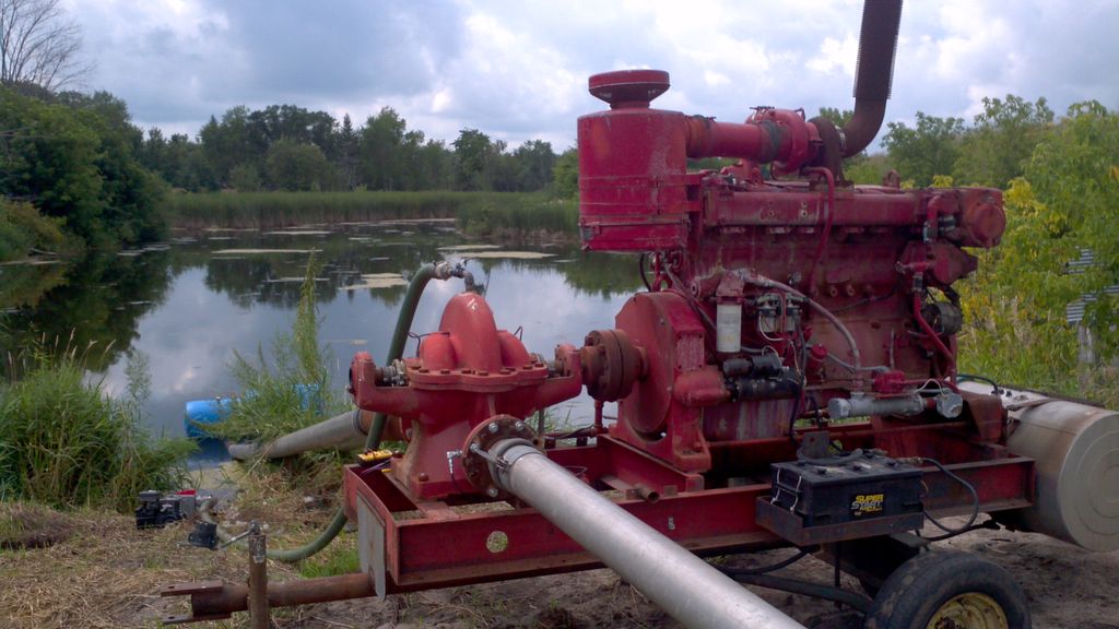
The irrigation system happened to be of the center pivot style. In this scenario there was a dug pit at one end of the field (that collects water). Water is pumped from the pond, out to the center of the field via 8” irrigation pipe (laid on the ground) to the center pivot. From there the multiple sections on wheels, all connected together (end to end) pivot around the pivot point, making a complete circle.
Here is a picture to give you an idea of what the system looks like.
Notice that each section has two wheels on the end, then the next section is coupled in series to the previous one with a rubber boot. This rubber boot allows the two sections to flex as they move across the field. As the irrigation system makes its way around the pivot point the sections at the end are required to move faster than the ones closer to the center in order to stay in a straight line. This is why there is a rubber boot separating the sections to allow them to flex as they try to maintain the straight system. Different contours of the field sometimes slow one or more sections, as the sections get behind they need to speed up and the sections closer to the pivot need to slow down in order for the system to travel the circle in unison. If the end sections were allowed to out run the inner sections or vise/versa, the rubber boot would rip off and water would poor into the field destroying the crops in that location. Not to mention that if the irrigation system was not shut down in a scenario like this it would destroy itself by wrapping around itself and bending up the framework and linkages.
Newer irrigation systems are driven across the field by electric motors, but not this one. This is an old pivot that relies on a water/mechanical drive system. The water drives a turbine at the end of each section; the turbine drives a shaft that goes down to a gear box that in turn drives the wheels. I should also mention that there is also a linkage arm on each section, and depending on the angle of the first section to the next, rotates a water valve that controls the amount of water allowed to travel through the water turbine driving the wheels. I.E. more water that section moves faster, less water flowing means that section would move slower allowing the sections after it to catch up.
OK, but what if something unforeseen happens, a flat tire on one of the sections. This would more than likely stop that section dead in its track. The other sections on either side of the dead section would still be trying to complete their cycle. This is where limit switches at each junction come into play. If these were not there, the sections would wrap around one another, and destroy things.
Step 2: Problem
Now that I have explained the system, here is the problem; there is a 14/2 direct burial UV rated wire that travels from the pump location (at the pond) out to both pivots and then from there along the pivots to each section junctions limit switch. (Did I not mention there were two of these center pivots? Well there are.)
This wire has been chewed, cut, and just plain abused over the last how many years and no longer has continuity through two of the three wires. Without this wire there is nothing to tell the pump to shut-down if a pivot gets outside the limits of operation.
The cost of 5-6000ft. of wire to replace the original wire was why outside my friend’s budget.
Step 3: Solution
Listening to his predicament I suggested he place a few wireless transceivers on each pivot and then another at the pump location. This in turn volunteered me to put together a quote on a bill of materials and inevitably build and install the wireless system.
Step 4: Build Progression
I had never worked with Xbee radios before but I had read about them and seen them in the parts catalog of my favorite vendor, and I thought they looked like a really cool solution to so many different problems. So I thought… what a great opportunity to work with them, and even better I didn’t have to pay to play!! J
So I set out to decide which Xbee radio I would need. There are so many different options to choose from! After careful consideration and reading countless blogs, postings, and reviews, I decided on the Xbee SB2. They were supposed to have more than enough rang for my application and they had mesh capabilities to allow me to reach the farthest pivot, if I couldn’t reach it directly. I could also use them stand-alone, meaning I didn’t need a microcontroller with them. This was important because I didn’t want to burn up batteries left and right.
I like to have actual paper documentation in from of me when I work. Datasheets, Manuals, Schematics, Design Notes, Pin Outs, all come in handy when I work and I like to be able to set two documents next to each other so I can cross reference as I work. So this was my next step.
After I had my paperwork in order and had read a little about the radios in question, their capabilities, power consumption, and other options. I felt I had a pretty good feel for what needed to be done.
Having never played with these radios before I wanted to do what anyone would want to do, I wanted to make them talk to each other! So I grabbed a few breadboard and wired one radio up with and LED on a output, and through a tactical button on an inputs on the second radio. The next step was downloading a program called X-CTU. This program allowed me to configure my radios to talk with one another. I should mention at this point that there are some great tutorials on the Web showing how this is done. After a little bit of puttsin around I was able to make my radios talk just fine.
Now with proof of concept I was ready to set down and design my project, draw up some schematics, and figure out the fun stuff like enclosures, and power sources.
Step 5: Design Phase
I want to apologies right of the bat. I was really good about taking pictures during this whole ordeal. Documenting my progress, failures, and triumphs, now do you think I can find those pictures? I can’t for the life of me figure out where they went or how they were deleted from my phone. So I am going to attempt to reconstruct this project from memory and I will try to get you pictures of the finished circuit boards and enclosures.
I knew I was going to need some sort of logic program in order to do everything I wanted as well as for future expansion of the system. For this I chose the Atmel 328 chip. Some may say this is way too much processor, but I had a few lying around and felt this would be a good way to use one up. The 328 chip had plenty of inputs/outputs and processing power for anything I might dream up. So the 328 it was.
I thought about the project for a while and drew up a list of what was required of my little wireless network. Let’s make a list now.
- Wireless communication from pivot 1 and pivot 2 back to pump location
- Monitor center pivot, shut down pump if system got out of alignment
- Shut down pump when the cycle is complete
- Shut down pump if radios fail to check in
- Shut down pump if there is a loss of pressure
- Shut down pump if engine temp is too high
- Shut down pump if engine loses oil pressure
- Test button to allow a com check of radios
- Minimal power consumption of radios( i.e. sleep mode)
For more detail: Irrigation logic controller/project log using Arduino