Summary of Interface Arduino and Color Sensor – RGB Sensor TCS230
This article explains how to read colors using the TCS230 RGB color sensor with an Arduino Uno. The TCS230 uses an array of photodiodes with red, green, blue, and clear filters to detect color light, converting it into a frequency-based square wave output. By setting pins S2 and S3 to specific combinations, the sensor reads each color component, which the Arduino then maps to RGB values. Pins S0 and S1 control the sensor's output frequency, affecting the sensitivity of readings. The tutorial guides interfacing the sensor with Arduino to display color values on a serial monitor.
Parts used in the TCS230 Color Sensor Project:
- TCS230 RGB Color Sensor
- Arduino Uno
- Connecting wires
- Power supply (5V)
In this article, we are going to read the colors using the TCS230 color sensor (RGB Sensor) and Arduino Uno. The TCS 230 color sensor senses the color light by using the photodiodes. The sensor converts the readings from the photodiode into a square wave by using the light to frequency converter. The frequency of these waves is directly proportional to the light intensity. Then the Arduino reads these square waves and gives us the values of the RGB colors. So let’s begin our tutorial on Interfacing Arduino and RGB Color Sensor TCS230.
Pin out – TCS230 (RGB Color Sensor)
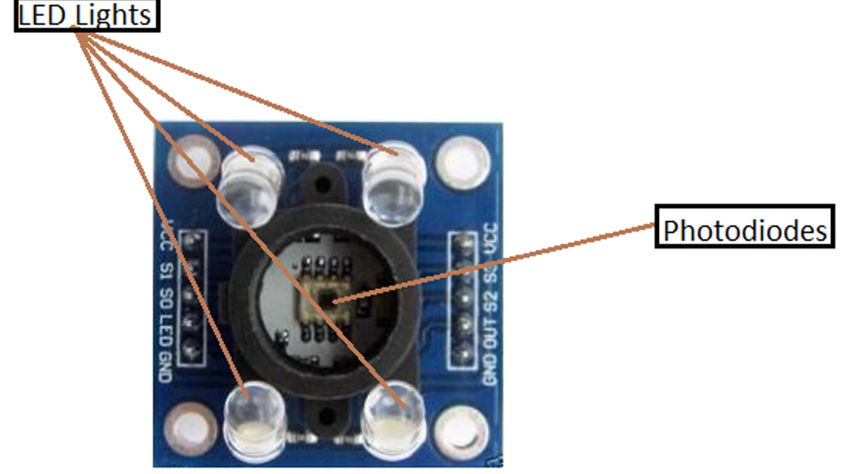
If you take a closer look at the sensor, you will see that it contains an array of photodiodes which are used to sense the color light. The sensor also consists of four LED lights.
The sensor has 10 pins; S0, S1 are for setting the frequency and S2, S3 are for reading the color values. The out pin is supposed to give the output to Arduino in the form of a square wave. The other pins are for powering the sensor.
Working of RGB Color Sensor
TCS230 color sensor consists of an 8X8 array of photodiodes. These photodiodes consist of three different color filters. 16 of them are red, 16 of them are green, 16 of them are blue and 16 of them are clear (No color). Every 16 photodiodes are connected in parallel. So, if we want to read colors, then we can read them by using the S2 and S3 pins. The pin combination for reading the RGB colors is as follows
| S2 | S3 | Color |
| LOW | LOW | Red |
| LOW | HIGH | Blue |
| HIGH | LOW | Clear |
| HIGH | HIGH | Green |
So with the help of pin combinations provided in the above table, we can read values of each color. First of all, we have to read the Red color by making both the S2 and S3 pin low. Then, we read the Green color by making both the pins high and finally, we read the Blue color by making the S2 pin low and S3 pin high. After that, we will map these values to 0-255 and show the color values on the serial monitor.
The sensor also has two more pins which are S0 and S1. These pins are used to set the frequency to 0%, 2%, 20% or 100%. The pin combination for setting the frequency using these pins is as follows
| S0 | S1 | Output Frequency |
| LOW | LOW | 0% |
| LOW | HIGH | 2% |
| HIGH | LOW | 20% |
| HIGH | HIGH | 100% |
In our code, the frequency is set at 20%. You can set the frequency to any other value (you desire), but the output values will change according to the set frequency and you will have to map the color values relative to the set frequency.
Read More: Interface Arduino and Color Sensor – RGB Sensor TCS230