Geoweaver is a student designed (team members Jia Wu, Mary Sek, and Jeff Maeshiro) robot created in the Creative Architecture Machines advanced options studio at the California College of the Arts (CCA) in San Francisco, California, taught by Jason Kelly Johnson of Future Cities Lab and Michael Shiloh. The design is based on a 12-servo hexapod with a glue gun extruder attached, is the culmination of about 60 days of research and prototyping, and, as far as we can Google, is the world’s first walking 3D printer. Although the robot’s official name is Geoweaver, it also goes by many aliases: Servo Killer, Eater of Shields, Melter of Wires, and Destroyer of Regulators, among many others. It is a very difficult and delicate machine, and is not a project to be tackled for the faint of heart.
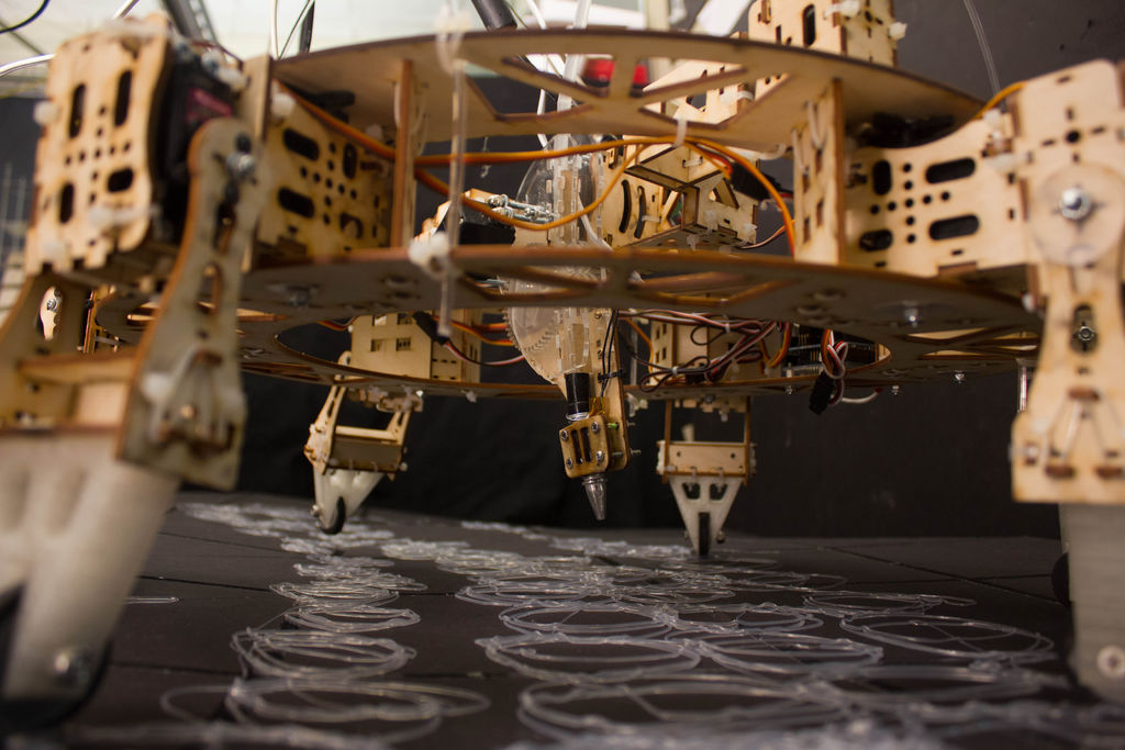
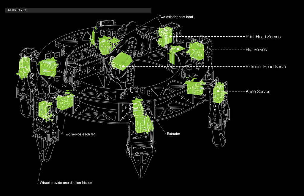
But if you do take it upon yourself to accept it’s challenges, it’s rewards are great: it is a six-legged, walking 3D printer. The center mechanism uses two servos to control the pendulum-like extruder head, allowing it to cover a basic XY plane (though curved to the surface of a sphere, see video above), and one servo for the extrusion gear that forces the glue-sticks through the “print head.” All of this can be controlled through the software Rhino 5, with the plug-ins Grasshopper and Firefly (developed by our professor Jason).
First, we must mention an Instructable that aided us at the start of our prototyping, the Hot Glue Gun Extruder for Your CNC Machine or 3D Printer project. It gave us a great starting point for our print head and we were grateful for the leg-up. Second, we utilized this tutorial to figure out how to do spirals in Grasshopper, though the spirals we made came out pretty intense.
Third, here is a video of the 62 day development process with different material tests and trial robot versions.
Lastly, this project was devilishly and deviously difficult and would not have been possible without our professor Jason Kelly Johnson’s guidance (even writing a custom Arduino-to-Firefly firmata for us to be able to use the servo shield, see Step 8). And of course our other professor Michael Shiloh’s sure-handed advice, most especially with the wheeled toes, a pretty nifty bit of mechanical innovation, if we are permitted to say so. Thanks also to Andrew Maxwell-Parish of CCA’s Hybrid Lab (and Instructables Artist In Residence ElectricSlim), your help with our projects was matched only by your enthusiasm for all of them. We are grateful to all three of you for your invaluable help.
Anyway, let’s get Instructablesing.
Required Items (tools):
- Vertical band saw
- Phillips/flathead screwdriver in multiple sizes
- Power drill and drill bits
- Wire cutters
- Needle nose pliers
- Measuring instruments, ruler or vastly preferably calipers
- Laser cutter
- 3D printer
Materials:
- 15 high torque servos (complete with the “+” shaped servo horns and servo center screws that should come with the kit
Bolts and locknuts (about 48 of them), or whatever bolts fit through your servo flange holes (the side holes). At least 3/8” long (enough for the 1/4” plastic or Al and a locknut to fit on there) - 1/8” at 24” x 48” sheet of plywood (for legs/center mechanism)
- 1/4” at 24” x 48” sheet of plywood (for body)
- 2 bags of hot glue
- 1/8” at 11” x 17” sheet of acrylic (for extruder)
- 3 bags of 100ct mini zip ties
- Small gauge wire
- Dowels
- 6 rubber sink washers
Required items (electronics):
- Arduino Uno
- Servo shield
- Computer
- Male headers
- Jumper wires (or single core wire suitable for breadboards)
- Servo extension cables
Required items (programs):
- Rhino 5
- Grasshopper plugin (for Rhino 5)
- Firefly plugin (for Grasshoppper)
- Arduino
Step 1: Laser Cut/3D Print Parts
*Keep your pieces organized and labeled, this makes it much easier to work. You will need a screwdriver, screws, drill, drill bits, zip ties, tape, sharpie, and nuts/bolts.
*Print or cut out a few extra pieces, they come in handy when one breaks or if you need a stand in piece
Next, 3D print the toes and tail. We used a Type A Next Generation Series 1, printing PLA with a 10% fill (to keep them light).
Step 2: Building the Hip Segment of the Leg
We found that the mechanics alongside the ratio of the pieces are imperative for the hexapod to walk smoothly (not to mention the code), but first you must stabilize the mechanics of the hexapod.
This includes figuring out the encasement’s for the each of the motors and their connections to each other. You want the hexapod to be both stable and light.
Also, take into account using slotted or dovetail connections with adjacent slots for quick zip tie connections and use the same dimensions on other parts so you can mix and match if need be. It makes construction fast and secure. Also, take into account the position of the servo. You want to create an environment where there is least torque for the motor, which could mean flipping the servos around, and MAKE SURE that joints are centered with the body of the hexapod. Any offset awkward pieces can affect the code and how the hexapod walks.
If you are using our design and have printed out the parts, use:
L.a (2)
E.i (2)
L.b
and fasten together with zip ties. Make sure that you secure a nut underneath the servo to attach to the body.
*Attach all horns onto servos and label each hip and knee. Preferably, the hips will all be one color tape with annotations, and the knee would be the other color with annotations.
* DO NOT restrict the servo by screwing in the center to any piece until servo is zeroed or calibrated. This could strip the servo, causing it to no longer work.
Step 3: Building the Knee Segment of the Leg
L.e
L.c
L.d
E.i (2)
L.f
L.g (2)
L.k,
L.j.
Fasten parts together with zip ties and then secure hip segment to the knee segment, do this for the six legs.