Summary of DIY Arduino Remote Control and Lego RC Vehicle!!
This project combines Lego, Arduino, and RC technology to create a custom servo-powered four-wheel drive and steering Lego RC car controlled via a bespoke Arduino-based remote. The car uses standard hobby servos controlled by an onboard Arduino and communicates wirelessly using XBee modules. The remote control features a 2.2” color LCD, joystick, potentiometers, buttons, and is housed in a custom laser-cut acrylic enclosure. The article details design decisions, 3D modeling in Autodesk Inventor, and practical tips on laser cutting and wiring, providing CAD files and code for replication.
Parts used in the Lego RC Vehicle and Arduino Remote Control Project:
- Lego medium-sized chassis with four-wheel drive and four-wheel steering drivetrain
- Four standard hobby servos
- Arduino microcontroller (for vehicle)
- Arduino microcontroller (for remote)
- XBee radio modules (one for vehicle, one for remote)
- Onboard power supply for RC car
- 2.2” LCD TFT color display (from Adafruit Industries)
- Joystick with analog horizontal and vertical output
- Two potentiometers with custom 3D-printed caps
- Four push-buttons in game-controller layout
- Laser-cut acrylic sheets for remote enclosure
- USB serial cable for remote control operation
- 9V battery for remote control power
- Computer-aided design software (Autodesk Inventor) for 3D modeling
- Measuring tools like a caliper (recommended)
UPDATE (8/29/13): Thank you readers for your enthusiasm and kind remarks regarding this project! It has been a tremendous journey since I started this project back in March, but I am very glad with the resulting product and the excitement with which it has been received by the maker community. Happy building! -Cyrus
Do you like Legos?
Do you like Arduinos?
Do you like RC things that you can bring to life with the flick of a thumb?
I certainly do, so today I’ll be showing you how to make something that combines all of the above into one and go over a ton of other useful techniques and best practices as well!
I’ll start by giving a brief description of what I made, and then I’ll follow with not just how to make it, but the reasons behind it too! By explaining all the steps involved (like the design, planning, 3D modelling, and even the Lego-building and laser-cutting!) and the decisions and thought process behind those steps (as well as the CAD files and code), I hope not only to share with you what you will need to make what I have, but also useful background and techniques that you can use not only in your own version of this project, but in all your other DIY projects too! Lastly, if there anything that I might have missed or that you need additional information or clarification about, or if you have any questions whatsoever, please feel free to ask me in the comments or to message me! Now lets get started!
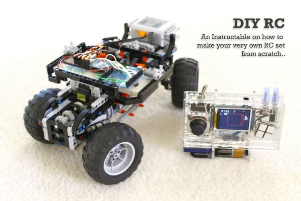
As you might have guessed from the title or seen in the video, the project I’ve been hinting towards consists of two parts: a completely custom Arduino remote control, and a servo-powered RC Lego car!
The Lego part of the RC vehicle is a medium-sized chassis built around a Lego drivetrain with four-wheel drive and four-wheel steering. The RC partis a set of four standard hobby servos powering the drivetrain; an Arduino, for controlling everything; and an XBEE radio, for communication with the remote control. There is also an onboard power supply (it’s an RC car! Of course it has one!).
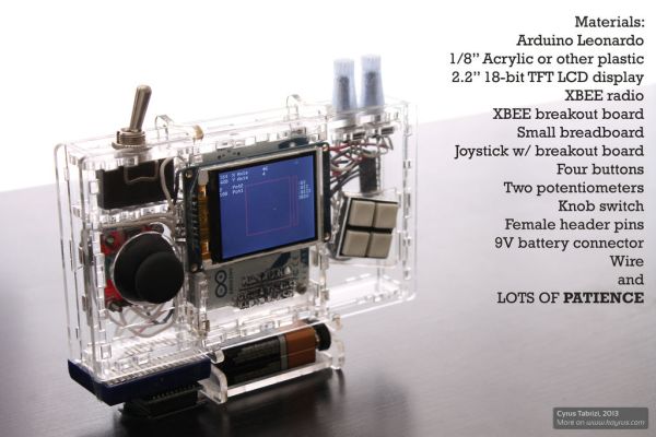
The second part of the project is the remote control. It’s about the size of aGameboy Advance; has a 2.2” LCD color display; is built around anArduino microcontroller; has a joystick, two potentiometers, and four buttons for input; and has the same type of XBEE radio module the RC vehicle does. All of this is housed in a custom enclosure made entirely from laser-cut acrylic. The remote control supports USB cable operation via the serial port on the Arduino, but it can also be operated off a 9V battery which can be mounted onboard, allowing the entire remote to be operated, well, remotely. Fun stuff.
Now that you know what you’ll be making, we can start actually making it.
Everything you’ll need file-wise is available for download on my site,Kayrus.com.
Here’s the link: www.kayrus.com/legos/diy_rc_zip (it should download automatically)
Included in the zip file are the latest Inventor part files (.ipt’s), the combined AutoCAD drawing (.dwg), and the latest Arduino code for the car and Handuino (.ino’s) and I’ll let you all know if I make updates or improvements to these!
Step 1: Designing the Remote Control..
The first step to making a remote control of your own design is deciding what types of inputs and outputs/feedback you want your remote control to have. You should also consider what form factor you want your remote to have, because this may affect what types of inputs and outputs you can fit in it.. You could make it like the stand-up RC car controllers, with their steering knobs and triggers; you could make it larger and give it two joysticks and a couple of flip switches, like those RC plane remotes, or you could make it to your heart’s content and give it a built-in speaker for voice feedback and force-sensitive touch control (that’s not a bad idea…)—the possibilities are only limited by yourimagination…and the size of the battery you want to carry along with you (I’m not kidding).
For my remote, I eventually decided that I wanted something I could carry in the palms of my hands, like the Gameboy Advance I used to play with many years ago; something with a variety of input types, because I wanted to be able to use it for different applications; and something with immersivefeedback capabilities so that I could know what was going on without the use of my computer.
Considering all this, I decided to give it a 2.2” LCD TFT color display from Adafruit Industries, because it was well-documented, well-priced, and knownfor its Arduino compatibility (most of Adafruit’s selection is!); four push-buttons in typical game-controller configuration; two potentiometers with custom 3D-printed caps for precise, but comfortable rotary input; and an off-the-shelf joystick with analog horizontal and vertical output (it was also supposed to let you click the joystick and use it as a button, but that function never actually worked as advertised).
After figuring out what I wanted, I did some conceptual sketches. This “design phase” is particularly important depending on how you plan to manufacture the actual enclosure (case, body etc.) of the remote. In my case, I planned to laser-cut the entire enclosure from transparent acrylic. This, however, is somewhat of a luxury if you’re a student (like myself). Luckily, my school happens to have one that I can use (if I had one of my own I would be using it all the time), but don’t worry if you don’t have access to one, because not only are there other materials you can make your enclosures from, but there are other means of getting your parts laser-cut or 3D-printed for you! For example, Ponoko is one online service that can ship you your custom-made parts, but if that’s too expensive or not your style, you should consider another building material, like Sugru, or consider cutting out your parts with an X-Acto knife. If you do use an X-Acto knife to cut out your parts, you probably won’t be able to have them fit together without adhesives, but it still functions just as well (the design I laser-cut fits together without tape or adhesives).
If you do have access to a laser-cutter or 3D-printer (or on online service that can provide you with those tools), you’ll have to design those parts using computer-aided design (CAD) software (like Inventor). The benefit of this type of software is that, in addition to being able to make parts precisely and with all sorts of features, you can also make the parts in an assembly and see how they all come together (we’ll go over this later). Before you can do this in a computer, though, you should plan it all out on paper.
To plan your design out, you need to start by getting all the dimensions of the parts you want to use. Often this can be done by looking up the dimensions or original spec sheets for the parts online, but occasionally you may have to measure them yourself in the case that a specific dimension is not available or if you want to double or triple-check something. In the case that you do want or have to measure something yourself, I recommend the use of a caliper—they’re great for making precise measurements quickly and conveniently so, if you don’t have one, I highly recommend picking one up from your local hardware store or online.
Once you have the dimensions of all your parts, you need to figure out thelayout of your remote. This includes not only the position of all the parts, but their orientation as well. At this stage, you don’t need to figure out exactly how the parts will be spaced out. Instead, it’s more critical that you figure out a design that will fit your needs and wants. In doing so, though, you still need to consider how the enclosure will come together, including where each part will go and what will keep them together (its a bit like a puzzle, but its fun!). You will also need to consider how you want to mount all the parts—you don’t need to figure out all the details now (like the diameter those holes need to be if you’re using nuts and bolts) but you should decide whether you want your parts to snap or press into place (most of mine do) or if you’re okay with hot-gluing them to each other or using some other adhesive or fastener.
While thinking about how to put the enclosure together, you should also be thinking about how to take it apart. This will depend on why you’re building the remote in the first place, but you need to think about the components inside the remote that you may want access to later on, and what type of access it is you want: or you okay with taking apart part of your remote just to reprogram it? What will you do if some wires disconnect or you need to replace a bad part? For my remote, I made it so that the back of the remote left the Arduino’s top face completely exposed—this may be bad in the long run protection-wise, but the access it gave me to the ports was critical to my improvement of the remote and will allow for other capabilities to be added later on without the need for taking the whole thing apart (although I still do that occasionally just for the fun of it) (and yes, you most certainly can design a removable panel that gives you both access AND protection—I just didn’t get around to it).
Lastly, but not least importantly, you need to think about wiring. Yes. Wiring. In larger remotes, you don’t really need to, but in smaller remotes like mine, where there’s not a lot of leeway between the Arduino and the components, you need to think about how everything will fit or if you need to have access holes here and there (I sure did), or you might find later that its extremely difficult to put together. EXTREMELY DIFFICULT. Everything in my version fits (albeit just barely) and I don’t want to discourage you from pushing the boundaries of enclosure-design, but take it from me: it’s much better to account for thingsbefore you’ve built them than afterwards (unless, of course, you’re open to building them again).
Step 2: A little redirecting..
Once you have a design done with pencil and paper, it’s time for you to turn it into a reality:
If you’re not planning to use a laser cutter to cut out your parts (or a 3D printer to print them), the following few sections may not be as useful to you (you’ll want to stick around though for the RC car and the wiring and programming of everything) because the following is about using Inventor to model your design.
If you plan to make my remote exactly as I have, then the following is alsonot necessary (although it may be useful here and in the future). Skip ahead to where I discuss the use of the laser cutter.
(NOTE: I don’t have a laser-cutter, but if I had one, my project output would increase ten-fold and it would enable many of my shelved projects to come alive once again)
Step 3: 3D Modeling in Autodesk Inventor
For those of you ARE going to laser cut (or 3D print) your own design, our journey continues into the world of CAD. I used Autodesk Inventor to create my enclosure digitally, because it is a powerful tool that is available for free as a student. While many other CAD programs are available (like SolidWorks, or, for free, Google Sketchup, 123D and plenty of others), I will be showing you how to do everything using Inventor.
The first step is to open Inventor and create a new Assembly (a Standard.iam). From here you’ll want to click the “Create” button in the “Assemble” window. Type in the desired name for your first part under “New Component Name” and the desired storage location for it (keep all your parts in the same folder), and then click OK. Click anywhere on screen and then click “Create 2D Sketch” and click somewhere on the screen to select your drawing surface.
For each part you will need to make, this and the rest is basically the same. You start by creating a 2D sketch with lines and different shapes. In doing so, you’ll use such tools like Dimension, Trim, and the different Constraints a lot, so try to become familiar with them—trust me, it’s worth it.
When drawing your part, it’s important that it be formed in a closed loop. An example of a closed loop is if I were to take a piece of string and attach each end to the other to form a circle. If the two ends were not attached, the string might still have a shape, but it wouldn’t be in a closed loop.
When your sketch is ready, click “Finish Sketch” and then head over to the “Extrude” command under the “3D model” tab—this is what turns your 2D surface into a 3D model. Once you’ve opened the Extrude window, hover your mouse over the body of your sketch. If you’ve done your sketch correctly, the surface of it should change color (mine appears light gray). If not, you need to go back and edit your sketch by clicking Cancel, right clicking on your sketch, and clicking “Edit Sketch.” If it does change color, though, you’re set. Click on the sketch and Inventor will show it as a 3D part. Chances are, though, that there are parts of your sketch that aren’t meant to be extruded. If that’s the case, click on them again while holding the CTRL key. You can go back and forth selecting all the closed loops until your part is exactly as it should be, minus its thickness—that comes next. Since we are primarily laser-cutting the various enclosure parts from a single sheet of plastic or acrylic, all the parts will have the same thickness (mine was 1/8”)—that thickness is the amount we will want to extrude our 2D drawings. This is under the “Extents” and “Distance” form in the “Extrude” window. Type in the thickness with the right unit of measurement and then click OK. Once its extruded you’re set! That’s your first 3D piece! Now click “Return” on the right and you’ll be back in your assembly and able to make another part.
This is all you’ll need to make your parts, but if you want to see your parts come together (which makes it a lot easier to visualize and plan out things), you’ll have to do a little more work (but I highly recommend it and its actually quite simple once you get the hang of it). Basically, you have to tell Inventor how the parts should stick to each other—this relationship is called a Constraint, and there are many different types Inventor has to offer. It would take a while to explain each and every one of them and their different options, but you can figure it out just as effectively and much more quickly by just playing around with it on your own (and its fun too). All you have to do is open the Constraints window (or press CTRL + C), select a type of constraint, click the little number “1” button under “Selections” and select the surface of one object, and then click the little number “2” button and select the surface of a second object. If everything is okay, the two objects should now move together and be constrained, but for the constraint to remain, you have to click OK or APPLY. By using different constraints on different parts of the objects, you can make it so that they all fit together without any freedom to move around. The best part of this is that you can edit your parts while they are together (be careful, though, because this may remove one or more of your existing constraints, but you can easily redo them).
For more detail: DIY Arduino Remote Control and Lego RC Vehicle!!