The Million Dollar Furby: We can rebuild him. We have the technology.
Continued from the previous Instructable where we excised Furby’s primitive brain , it’s now time to replace it with something greater.
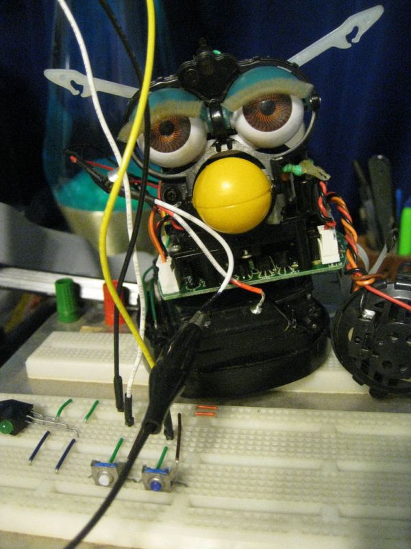
This Instructable will detail how to install a new microcontroller in place of Furby’s old brain, making him into a fully controllable robot puppet. We might not have a million dollars to rebuild him, but we won’t need it: I’ll be using the Arduino, a microprocessor and board which can cost under $20.
Note 1: These steps are about the old Furby with the moving plastic eyes (Tiger Electronics, 1998-2001). The new one is different in many ways!
Note 2: WARNING: This is not really a beginner’s project. I really tried to make it “basic,” but it didn’t work out. I’d say it’s somewhere between “Advanced” and “Jedi.” Sorry about that. Therefore, I’ve had to assume you can solder, code, and even build simple robots yourself.
I’ll get you started to the point where we write some code, but after that you are on your own! The reason for this is, the state of microcontroller boards changes so fast, any code I put in here will be obsolete in weeks to months, and the hardware obsolete within a few short year. Instead, I’ll provide the pinouts so you can use whatever board you want, and loose outlines for how control software could work.
Step 1: What You’ll Need
Here’s what you’ll need for this project:
- a Furby, preferably already disassembled (from the previous instructions)
- a microcontroller and board
- I’m using an Arduino Mega 2560, but it could just as easily be one of the lighter Arduinos
- a computer to develop and upload the code
- some wires (I’m using a ribbon cable)
- a way to connect the wires to the microcontroller board – I’m using pins to make everything tidy
- soldering equipment:
- soldering iron
- solder
- needle-nose pliers
- wire cutters
- wire stripper
- a few buttons
Optional but very helpful:
- some way to hold wire and parts while you solder them
- a power supply (to run Furby’s motor)
- more wire pins to run:
- from Furby’s PCB to his base
- from Furby’s PCB to his body
- a protoboard
Step 2: Furby board pinouts
Consult my previous tutorial to dissect Furby and get to his board.
Remove the daughter boards that hold furby’s processor and speech synthesizer. I have a separate project to (someday) use the speech synthesizer board… someday!
Here’s a pinout for the board. We won’t be using all of them, but here they are for future reference. Numbered counter clockwise from the bottom right:
MAIN BOARD
- 02 – /FEED – sensor, negative logic – Furby’s tongue
- 03 – MOTOR REVERSE – one of the two inputs to Furby’s H-bridge and motor which controls his eyes, ears, mouth, and body tilt
- 04 – MOTOR FORWARD – the other H-bridge input
- 05 – GEAR LED – a LED which lights up the slots in the gear to detect motor movement – must be on for Motor control!
- 06 – /POWER DOWN – must be raised HIGH for Furby’s hardware to work
- 07 – SOUND IN – wired to Furby’s primitive microphone
- 08 – LIGHT IN – wired to Furby’s primitive light sensor in his forehead
- 09 – UPSIDE DOWN? – raised HIGH if Furby’s tilt sensor is all the way upside down
- 10 – TILT? – raised HIGH if Furby’s tilt sensor is tilted. Note that there is actually an unused third terminal on the tilt sensor which is on if Furby is “level”
- 11 – SELECT EEPROM – one of a few data-driven pins. This one selects Furby’s memory, which I won’t be addressing here.
- 12 – ? (data line to 2nd board)
- 13 – IR IN – infrared communication Furby uses to talk to other Furbys
- 14 – SERIAL IN – used to control the speech synth and memory
- 15 – ? (data line to 2nd board)
- 16 – ? (data line to 2nd board)
- 17 – SERIAL OUT – used to control the speech synth and memory
- 18 – SERIAL CLK – used to control the speech synth and memory
- 19 – /RESET – negative logic “reset” switch under Furby’s tail
- 20 – TUMMY – the button on Furby’s stomach
- 21 – /BACK – the negative logic button on Furby’s back
- 22 – GEAR ROTATION – HIGH when sensor sees light through the slots in the gear to detect motor movement – an essential part of Furby’s Motor control
- 23 – /CAM HOME – negative logic sensor which goes on once a revolution of Furby’s gear
- 24 – GND for the board
- 25 – +5.31 V power for the board
SPEECH SYNTH BOARD
- 01 – 06 – data lines, SERIAL IN/OUT/CLK
- 07 – GND
- 08 – +6V
- 09 – SPEAKER+ – one of two contacts for the belly speaker
- 10 – SPEAKER- – one of two contacts for the belly speaker
- 11 – IR OUT – infrared communication Furby uses to talk to other Furbys
- 12 – data line
Step 3: Connecting wire ribbon
Next we connect wires to these contacts.
I’m using wire ribbon to make things cleaner. This is 25 wires all attached together.
The main daughterboard has 25 contacts by itself – however some need not be connected to the ribbon
- I’m using an Arduino board, so we don’t need power or ground in the ribbon
- the speech synthesizer has been removed as well, so we don’t really need any of the SERIAL data lines
However, we DO need the remaining sensor/actuator contacts from the second daughterboard – mainly the speaker outputs
Optionally we could:
- wire the IR output from the second daughterboard… just in case we want to use IR communications later
- wire the SERIAL data lines anyway – why? so we could access the Furby “memory” and retrieve his name
However, I don’t have enough wires in my ribbon, so I’ll just connect the speakers and IR without any data lines.
So:
- First map out which wires go to which contacts
- Make sure each wire is long enough to get to its contact!
- strip the wire ends
- solder
Step 4: Connect microcontroller pins
On the other end of the ribbon is our microcontroller.
We need to make sure the ribbon contacts are compatible with the microcontroller.
Since I’m using an Arduino, and it already has header pins on its board, I need to attach female pins to the ribbon.
Now we’ve plugged in all the sensor outputs and motor inputs.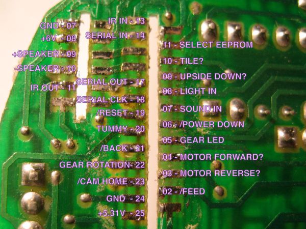
Step 5: Define the pins on the board and connect
This part is a matter of preference, but when I write code, I prefer not to memorize which pins are plugged into which functions.
Thus I’ve defined at the top of the code which functions are which pins.
But, because sometimes I unplug the ribbon and forget which went where, I also defined the ribbon pins.
Therefore, I have three sets of #defines .
A sample – here’s the code that defines the motor functions:
First I define the functions. These are the names I use in the code.
They are defined in terms of the pins on the board
#define MOTOR_FORWARD U1_FORWARDMOTOR
#define MOTOR_REVERSE U1_REVERSEMOTOR
Next I define which pins on the board go to which ribbon wires:
#define U1_REVERSEMOTOR RIBBON_A_8
#define U1_FORWARDMOTOR RIBBON_A_7
Finally the ribbon maps to the pins on the arduino board. These may get redefined if I plug the ribbon into other parts of the board:
#define RIBBON_A_7 36
#define RIBBON_A_8 38
NOTE: What’s with all the RIBBON_A business you ask?
I broke the ribbon up into parts, and named them to keep track of them:
- RIBBON_A = large ribbon – 10 pins
- RIBBON_B = small ribbon – 2 pins
- RIBBON_C = medium ribbon – 7 pins
- RIBBON_D = small ribbon – 3 pins
For my setup, I’ve arranged them in a 11×2 grid on the arduino Mega so they are compact.
- RIBBON_A + RIBBON_B_0
- RIBBON_C + RIBBON_D + RIBBON_B_1
Lastly, I define where my buttons go. Because they are “negative logic” buttons, that is LOW when pressed, their names start with “X” :
#define XBUTTON_FWD 52
#define XBUTTON_REV 53
For more detail: Control a Furby with Arduino (or other microcontroller)