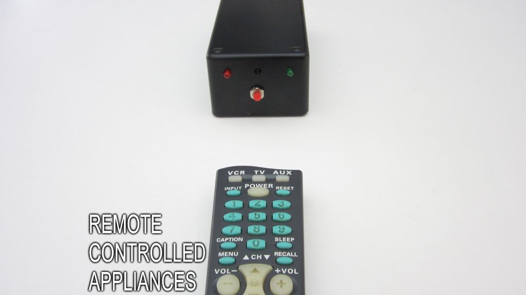
Most of the buttons on a remote control are never used. So why not use them to control appliances and other electronics around your house. In this project, I am going to show you how to use an Arduino to decode the signal from your remote and use it to make an outlet switch that can turn your electronics on and off.
When you are done, you will be able to control lights, fans and even your coffee maker with your TV remote.
Step 1: Materials
Materials:
Arduino Microcontroller
AC Power Adapter For the Arduino
38 kHz Infrared Receiver Module (Radio Shack part# 276-640)
Red LED
Green LED
Momentary Pushbutton Switch
Two 100 ohm Resistors
10 kohm Resistor
Diode
5V Relay or Relay Shield
Printed Circuit Board
Plastic Project Housing
Extension Cord
Tools:
Wire Strippers
Soldering Iron and Solder
Drill and Bit Set
Sharp Knife
Hot Glue Gun
Step 2: Download and Install the IR Remote Library
The first thing that you need to do for this project is download the library zip file. You can find it here: https://github.com/shirriff/Arduino-IRremote
Click “Download ZIP” on the right side of the page and save the zip file. Then unzip it. Rename the folder “IRRemote” (unless that name is already being used).
Then copy the folder into your libraries directory. The libraries directory should contain the folder “IRremote.” If for some reason you already have a folder with this name, then you may need to rename it. The IRremote folder should contain the files. A lot of problems experienced when uploaded in the code, are caused be the library not being loaded in the correct location.
Step 3: The Arduino Code
#include <IRremote.h>
int RECV_PIN = 11;
IRrecv irrecv(RECV_PIN);
decode_results results;
unsigned long CurrentValue = 0;
unsigned long StoredCode = 0;
const int buttonPin = 6; // the number of the pushbutton pin
const int ledPin = 4; // the number of the LED pin
const int outputPin = 3; // the number of the output LED pin
const int relayPin = 2; // the number of the relay pin
int buttonState = 0; // variable for reading the pushbutton status
int RecordState = 0; //is the reciever in record mode
int outputState = 1; //is the output on or off
void setup()
{
Serial.begin(9600);
irrecv.enableIRIn(); // Start the receiver
// initialize the LED pin as an output:
pinMode(ledPin, OUTPUT);
// initialize the pushbutton pin as an input:
pinMode(outputPin, OUTPUT);
// initialize the pushbutton pin as an input: pinMode(buttonPin, INPUT);
pinMode(relayPin, OUTPUT);
// initialize the pushbutton pin as an input: pinMode(buttonPin, INPUT);
}
void loop() {
// read the state of the pushbutton value:
buttonState = digitalRead(buttonPin);
// if a signal is detected, store the value
if (irrecv.decode(&results)) {
CurrentValue = (results.value);
// if the recieved value equals the programed value, then toggle the output state
if(CurrentValue == StoredCode) {
outputState = !outputState;
}
// if the record mode is activated store the current value as the programed value
if (RecordState == 1) {
StoredCode = CurrentValue;
RecordState = 0;
digitalWrite(ledPin, LOW);
Serial.println(StoredCode); //displays stored code for reference
}
// Receive the next value
irrecv.resume();
}
else //if no signal is detected, then the current value is 0
{
CurrentValue = 0;
}
// check if the record button is pressed.
// if it is, the buttonState is HIGH:
if (buttonState == HIGH) {
//wait for the button to be released
while (buttonState == HIGH) {
buttonState = digitalRead(buttonPin);
}
//turn on the LED to indicate that record mode is on
digitalWrite(ledPin, HIGH);
RecordState = 1;
}
//set the appropriate output state
if(outputState == 1) {
digitalWrite(outputPin, HIGH);
digitalWrite(relayPin, HIGH);
}
else {
digitalWrite(outputPin, LOW);
digitalWrite(relayPin, LOW);
}
}
Step 4: The Circuit
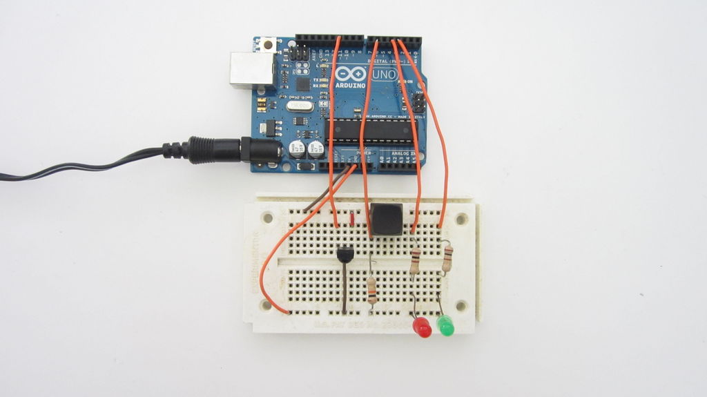
The circuit also has two indicator LEDs. One indicates that the receiver is in programming mode and the other indicates whether the output is on or off. One end of each LED is connected to GND. The other end is connected to a 100 ohm series resistor. The resistors are then connected to digital pins 3 and 4.
A momentary switch is used to set programming mode. One end of the switch is connected to 5V. The other end of the switch is connected to digital pin 6 and a 10 kohm resistor. The other end of the resistor is connected to GND.
An optional relay/relay shield can be connected to digital pin 2 and GND.
You can add any additional outputs that you want. This can let you control multiple devices or multiple functions on the same device.