Summary of DNA Melting Part 2: Lock-in Amplifier and Temperature Control
This article outlines Part 2 of the DNA Melting Lab, focusing on enhancing instrument control and reducing noise. It introduces a PWM heater controller to manage heating rates and an op-amp with a lock-in amplifier system to detect fluorescent signals from the DNA sample more accurately. The guide details the assembly of a new PCB heater-cooler board to regulate TECs, ensuring precise temperature management for reliable data collection.
Parts used in the DNA Melting Lab Part 2:
- PWM heater controller
- Op-amp
- Blue LED
- Photodiode
- Lock-in amplifier
- PCB heater-cooler board
- Red/black connector cable
- Nylon feet
- Diablotek power supply
- Sample holder
- TECs (Thermoelectric Coolers)
- RTD (Resistance Temperature Detector)
- Sample vial
In Part 2 of the DNA Melting Lab you will make revisions to allow greater control of your instrument and to reduce the effects of noise. You will add a pulse-width modulation (PWM) heater controller to enable careful control of the heating and cooling rates of the DNA sample. This will allow you to maintain a melting rate below the melting rate of the DNA and to work around the thermal lag of the instrument.
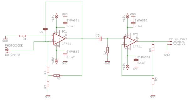
You will use an op-amp to enable modulation of the light flux emitted from the blue LED. The modulated illumination will then result in an oscillating amount of fluorescent light flux from the DNA sample. The oscillating flux signal will be detected by a photodiode and then amplified and demodulated using a lock-in amplifier. The modulation will allow you to place your signal in a low-noise area of the frequency spectrum, and the lock-in will allow you to recover the signal. Review your lecture notes, find an instructor, and review the Understanding the lock-in amplifier wiki page.
Add a heater/cooler/controller board to thermal subsystem
In your instrument, both the actual and apparent behavior of the melting DNA sample are dependent on the heating and cooling rate of the sample holder. The temperature of the DNA sample always lags behind that of the sample holder. If the rates are reasonable, then the lag is not severe and a correction can be applied to the measured sample holder temperature to predict the sample temperature. If, on the other hand, the rates are too
high, then the correction becomes unreliable. In addition, the melting and annealing reactions have a time scale associated with them as well. You will control the rates to yield the best data possible with your instrument. To do this, a specially-designed printed circuit boards (PCB) is provided. The PCB controls the current supplied to the TECs in contact with the smaple holder. Since the sample holder is aluminum, the parts of it in contact with
the TEC, the RTD and the sample vial are all identical for reasonable heating and cooling rates. The PCB will be controlled by a modified version of the software, which you will implement later on in Part 2.
Parts
Gather the following components:
- 1 PCB heater-cooler board from the Center Cabinets or the East Cabinets.
- 1 red/black connector cable from the East Cabinets.
Assembly
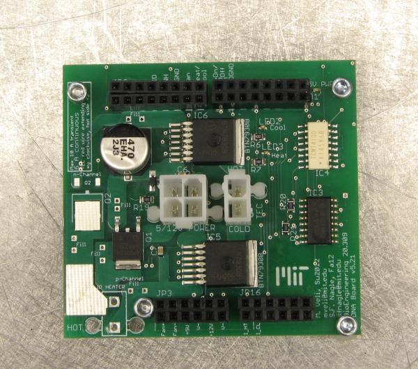
Points of connection are labeled on the PCB and described in the table and figure below. Refer to both in the instructions that follow.
- Disconnect the yellow/white cable between the supply and the TEC stack.
- Place the PCB in the pre-drilled holes on the sheet metal support bracket.
- If the nylon “feet” are missing, add them now. They are in the DNA Melting drawer at the right of the Wet Bench.
- Turn off the Diablotek power supply.
- Connect the Diablotek and check power
- Connect the Diablotek 4-pin/3-color power supply connector to the 4-pin connector on the PCB.
- Quickly cycle the Diablotek power to confirm a green power status light in the upper right corner of the PCB.
- Confirm that the Diablotek is off.
For more detail: DNA Melting Part 2: Lock-in Amplifier and Temperature Control
- How does the PWM heater controller improve the experiment?
It enables careful control of heating and cooling rates to maintain a melting rate below that of the DNA and work around thermal lag. - Why is a lock-in amplifier used in this setup?
The modulation places the signal in a low-noise area of the frequency spectrum, allowing the lock-in amplifier to recover it. - What component modulates the light flux emitted from the blue LED?
An op-amp is used to enable modulation of the light flux. - Does the sample temperature always match the sample holder temperature?
No, the temperature of the DNA sample always lags behind that of the sample holder. - What happens if the heating and cooling rates are too high?
The correction applied to predict sample temperature becomes unreliable. - How do you confirm the Diablotek power supply is working after connection?
You quickly cycle the power to confirm a green power status light appears in the upper right corner of the PCB. - What is the purpose of the specially-designed printed circuit board provided?
The PCB controls the current supplied to the TECs in contact with the sample holder. - Where can you find the nylon feet if they are missing?
The nylon feet are located in the DNA Melting drawer at the right of the Wet Bench.