Summary of Clap Switch using Arduino
This project describes creating a Clap ON Clap OFF switch using an Arduino UNO and a condenser microphone to detect clap sounds. The microphone captures sound signals, which are amplified and passed through a high-pass filter before being converted to digital signals by the Arduino's ADC. Each detected peak (clap) toggles an LED to switch the device on or off. This approach replaces earlier versions using 555 Timer ICs, utilizing sound as a control input to the system.
Parts used in the Clap ON Clap OFF switch project:
- ARDUINO UNO
- Power supply (5V)
- Condenser microphone (MIC)
- 2N3904 NPN transistor
- 100nF capacitors (2 pieces)
- 100µF capacitor
- 1KΩ resistor
- 1MΩ resistor
- 15KΩ resistors (2 pieces)
- LED
- Breadboard
- Connecting wires
In this project we are going to make Clapper circuit using the concept of ADC (Analog to Digital Conversion) in ARDUINO UNO. We are going to use a MIC and Uno to sense the sound and trigger a response. This Clap ON Clap OFF switch basically turns ON or OFF the device, by using the clap sound, as switch. We have previously built Clap switch and Clap ON Clap OFF switch, using 555 Timer IC.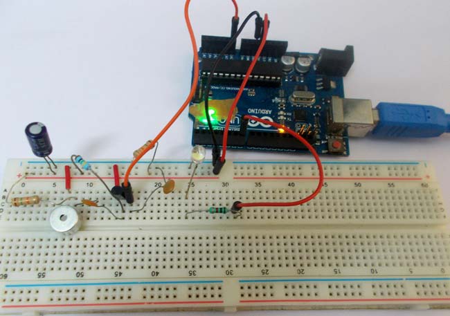
On clapping there will be a peak signal at the MIC which is much higher than normal, this signal is fed to the amplifier, though a High Pass Filter. This amplified voltage signal is fed to ADC, which converts this high voltage into a number. So there will be a peak in the ADC reading of the UNO. On this peak detection we will toggle an LED on the board, on each clap. This project has been explained in detail below.
MIC or Microphone is a sound sensing transducer, which basically converts sound energy into electrical energy, so with this sensor we have sound as changing voltage. We usually record or sense sound through this device. This transducer is used in all mobile phones and laptops. A typical MIC looks like,
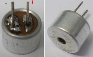
Determining the polarity of Condenser Mic:
MIC has two terminals one is positive and another is negative. Mic polarity can be found using a Multi-Meter. Take the positive probe of Multi-Meter (put the meter in DIODE TESTING mode) and connect it to one terminal of MIC and the negative probe to the other terminal of MIC. If you get the readings on the screen then the terminal of positive (MIC) is at negative terminal of Multi-Meter. Or you can simply find the terminals by looking at it, the negative terminal has two or three soldering lines, connected to the metal case of the mic. This connectivity, from negative terminal to its metal case can also be tested using continuity tester, to find out the negative terminal.
Components Required:
Hardware:
- ARDUINO UNO, power supply (5v), a condenser mic (explained above)
- 2N3904 NPN transistor,
- 100nF capacitors (2 pieces), one 100uF capacitor,
- 1K Ω resistor, 1MΩ resistor, 15KΩ resistor (2 pieces), one LED,
And Breadboard & Connecting wires.
Software: Arduino IDE – Arduino nightly.
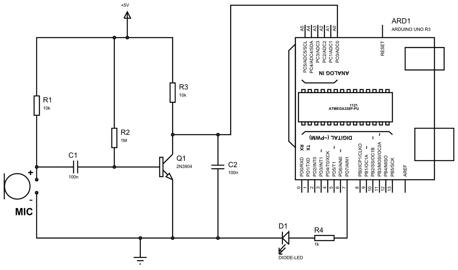
Circuit Diagram and Working Explanation:
The circuit diagram of the clapper circuit is shown in below figure:

Read More: Clap Switch using Arduino