In this article we are going to take a detailed look at how to build the driving circuit for the 8x8x8 LED cube. In other words we are going to design and analyze the circuit which translates the signals coming from the Arduino to appropriate currents passing through each of the LEDs, so that the desired animations can be created. We will go through the schematic, check the needed parts and we are going to see how to build the circuit exactly. If you haven’t read the introduction part yet, which talks about what we are trying to achieve in general, it’s probably a good idea to read it before we dive into the details of the driving circuit.
Power consumption
A very important thing to consider when designing a driving circuit for an LED cube is the maximum possible power consumption of the system, because the components and the power supply need to be chosen accordingly. The components that will drain most of the current are obviously the LEDs. Our cube is going to be one that is used with multiplexing (but we will do the multiplexing from the software, so we don’t need to worry about hardware multiplexing). This means that at any given time only one horizontal layer (plane) can be lit. In other words we need to plan for a maximum of N*N LEDs consuming power. In the 8x8x8 cube this means that we’ll have to take into account the power consumption of 64 LEDs, but if you are building a cube of a different size, you’ll need to adjust the calculations accordingly.
So how much current can an LED drain? Well, that depends on the value of the current limiting resistors that we use for each one of them. But the standard 3 mm (or 5 mm) LEDs of today are usually rated at 20 mA. We will design the circuit to be able to handle 20 mA of current per LED because there is a wide selection of LEDs out there and you might need to really give them 20 mA to shine brightly. However, I have found that most LEDs need much less current in order to shine brightly. For my own LED cube I have used standard 3 mm bright blue LEDs. For these the optimal brightness is obtained at 1.5 mA, which is obviously much less than their 20 mA rating. I’d like to emphasize here that figuring out the optimal brightness of you LEDs before you start building the cube’s driving circuit is very important. If your LEDs won’t be bright enough, the cube will look pale and that’s not something that we want. On the other hand, if the LEDs will be too bright, they will shine through the LED which is above them in the cube and it will seem that the above LED is also lit. This is even worse than a pale cube. So experiment with your LEDs, in darkness and in daylight and determine how much current they need to shine with the exact brightness that is needed. Note that the value of the used current limiting resistors will also depend on the color of the LEDs because LEDs of different colors have different voltage drops. Here is a quick reference of the LED forward voltage values by color.
Getting back to the circuit design, we will plan for a maximum current of 20 mA per LED and a maximum of 64 LEDs being lit simultaneously. That means a total consumption of 1.28 A. That’s quite a lot and we’ll need a power supply rated at least at 1.5 A, preferably at 2 A. Should you decide to feed your LEDs with less current, a smaller power supply will suffice. In my circuit I have given them about 1.5 mA, so for 64 LEDs that’s a total of only 92 mA and yet the brightness is good enough. For 3 mm or 5 mm white or blue LEDs most likely the same current values can be used. For other colors you might need to give them a bit more current or even if the same amount of current will be enough, you’ll need resistors of different value.
Let’s also keep in mind that the LEDs are not the only components in the circuit which consume power. The other components (like MOSFETS and shift registers) also use up some current, but that is close to a negligible value. There is however something else. The multiplexed cube needs to switch between the layers very fast, in a matter of a few milliseconds or even less than one millisecond. Some of the components, like the MOSFETs which switch the layers, need time to shut off. I have found that some resistors are needed between the anode layers and the ground and the cathode columns and the positive voltage in order to help some currents go away after switching layers, otherwise they will go away through the LEDs and that will result in ghosting (when a layer is switched on, the previous layer is also dimly lit, which looks very bad). So, to get rid of this ghosting, I have added a 1K resistor between each anode layer and the ground and a 10K resistor between each cathode column and the positive voltage. In a 8x8x8 LED cube we have 8 anode layers and 64 cathode columns. Given the fact that the whole circuit functions at 5V, this means that the resistors between the anode layers and the ground will generate a total current consumption of 8*5 mA = 40 mA. The resistors between the cathode columns and the positive voltage will generate a total of 64*0.5 = 32 mA current consumption. That’s 72 mA overall. Unfortunately this is a passive power consumption, meaning that the cube will consume at least this this much, even if all the LEDs are off.
Finally, let’s not forget the power consumption of the Arduino which powers the cube. You will most likely want to power it from the same supply unit, so it too adds to the consumption. This will depend on the exact model that you use but even the most power hungry ones will not eat up more than 200 mA. Unfortunately it’s likely that we’ll need a model which uses quite some current (but not more than 200 mA) because the code that generates the animations will need a few kilobytes of memory, so a more powerful microcontroller (with enough memory) is needed for it.
Schematic
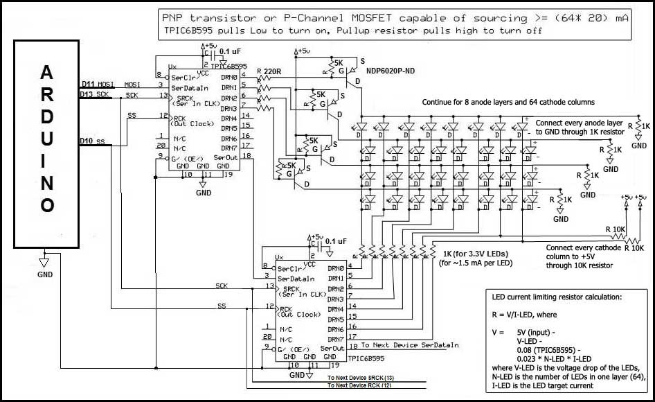
So, without further ado, allow me to present the schematic of the driving circuit. Please note that it was designed by Robert Patterson, also known as CrossRoads at the official Arduino forum. It’s he who we have to thank for this wonderful design. To check out more of his great circuits, visit his website at http://www.crossroadsfencing.com/BobuinoRev17/.
Serial communication between the Arduino and the shift registers
As explained earlier, in the introduction, we are going to use serial-in, parallel-out shift registers in our LED cube driving circuit, so that we can minimize the connections between the Arduino and the circuit. The data between the Arduino and the shift registers will be transferred via serial communication, through SPI. The Arduino will have the role of the master and the shift registers will be the slaves. The shift registers can be chained, meaning that the output of the first one can be fed into the second one, the output of the second one can be fed into the third one, and so on. This allows us to minimize the communication lines between the Arduino and the driving circuit because the Arduino only needs to send data to the first shift register in the chain and this first shift register will pass on the data, until it reaches the very last one. To understand how shift register work, check out this great video by Kevin Darrah:
In a circuit which drives an LED cube made of N*N*N LEDs, the number of shift registers needed is N+1 (this is true if N<=8). One is needed to switch on/off the anode planes and the rest of N shift registers are needed to switch the cathode columns. The TPIC6B595 shift registers that we use have 8 outputs, meaning that each shift register can drive up to 8 anode layers or 8 cathode columns. The first shift register in the chain is assigned to the anode layers because switching these is the most important and data from the Arduino reaches this shift register first. If you consult the datasheet of the TPIC6B595 shift register, you will see that the data is propagated from one shift register to the next very fast, in a matter of a few nanoseconds, so if the Arduino needs to send some data even to the last shift register in the chain, it can just push it through the whole chain quite fast, until it reaches the last one.
The most important thing to understand is that whenever the Arduino wants to change the state of any LED in the cube, it will actually update all the shift registers in the chain (with (N+1)*8 bits of data in total). It will first send the 8 bits of data which need to be in the last shift register and these first 8 bits will go into the first shift register first, but when it will send the next 8 bits of data, the first shift register will make room for these next 8 bits by flushing out the first 8 bits, into the next shift register. The third transfer of 8 bits will push the data from the second shift register into the third one and from the first shift register into the second one. This way, after N+1 transfers of 8 bits, the first 8 bits will arrive into the last shift register in the chain, the second 8 bits will arrive into the one before the last and so on. The 8 bits which are sent out last will remain in the first shift register in the chain. This means that the state of the cube changes all the time during the communication between the Arduino and the shift registers, but this happens so fast (in a few hundred milliseconds at most) that the human eye will not see any of it happening. Quite a nifty trick.
Unlike most LED cube driving circuits out there, which use the popular and ridiculously cheap 74HC595 shift register, ours has TPIC6B595 shift registers in it. This is because we plan for relatively high currents (if we really plan to give a maximum of 20 mA to the LEDs) and we need to sync the current, not source it, because of our anode layer and cathode column design. But the TPIC6B595 is also cheap enough and it switches fast enough (in a few nanoseconds).
As shown on the schematic, only 3 pins are needed for the serial communication between the Arduino and the first shift register: master out, slave in (MOSI), clock (SLCK) and slave select (SS). The MOSI pin of the Arduino is connected to the SER IN pin of the first shift register in the chain, than the SER OUT pin of the first shift register goes to the SER IN of the second one and so on. This is how the shift registers are chained (this is how data goes from one to the next). The SCK (SCLK) Arduino pin is connected to the SRCK pin of all shift registers. The SS Arduino pin is also connected to all the shift registers, to their RCK pin.
Switching the anode layers with MOSFETS
While only a maximum of 20 mA can travel through each cathode column (which means that the cathode column can be connected directly to an output pin of a TPI6B595 shift register), the situation of the anode layers is different. They can have up to N*N LEDs lit up at once, so in an 8*8*8 LED cube up to 1.28 A of current can go into an anode layer. This can obviously not be handled by the output of the shift register which controls the anode layers, so we need something that decouples these large currents from the anode layers’ shift register. The solution is to use NDP6020P MOSFETS. It’s important to note that not only can they handle the maximum possible current that goes through the anode layers, but also they switch on/off fast enough (in a matter of a few hundred nanoseconds in the worst case). This is crucial because of the multiplexing used in our cube (switching between layers very fast to trick the human eye and make it think that all the layers are on, while in reality only one is). The ability of the NDP6020P MOSFETS to switch very fast is explained by their low Rds(on) value (seen in their datasheet). This is what sets them apart from many similar components that exist.
Each output of the first shift register (which handles the anode layers) is connected to an NDP6020P MOSFET’s gate through a 220 Ohm resistor. The source pin of the MOSFETS is connected to the 5V power, from where it directs the current to the appropriate anode layer of the cube (through the drain pin) when the shift register switches it on. When the appropriate output pin of the TPIC6B595 is switched on, the output pin acts as low, switching the MOSFET on. When the shift register’s output pin is switched off, the MOSFET is pulled high through the pull-up resistor between its gate and the 5V positive voltage. For this pull-up resistor 5.6K or 3.3K values are fine.
Limiting the LED currents
The brightness of the LEDs in the cube is determined by how much current we allow to flow through them. This is determined by the current limiting resistors that are connected between the LED cathodes and the outputs of the N shift registers which drive the cathode columns. This means that for a cube consisting of N*N*N LEDs we are going to need N*N current limiting resistors of the same value. The value of these resistors depends on how much current we want to give the LEDs, as discussed earlier. The value of the current further depends on the type and color of the LEDs. However, we know that our circuit works with 5V, but the MOSFETS and the shift registers loose some of that voltage, so the value of the current limiting resistors should be calculated with approximately 4.89V (suing Ohm’s law or the LED resistor calculator).
Eliminating ghosting
Unfortunately the clean design of the driving circuit has to be complicated a bit by adding some resistors between the positive voltage and the cathode columns and between the ground and the anode layers respectively. Their role is to help dissipate some currents which would otherwise go through the LEDs when the LEDs are actually switched off. This would result in some ugly ghosting (some LEDs lighting up in a dim fashion when they are supposed to be completely off). The software also needs to be aware of this and wait for a few microseconds between switching one anode layer off and switching the next one on (think of multiplexing). During these few microseconds these unwanted currents are directed away through the resistors. Between the cathode columns and the positive voltage we will add 10K resistors. Between the anode layers and the ground we need to add 1K resistors.
I have struggled a lot until I have finally managed to figure out this solution for the ghosting issue that existed in my test cube. I wish to thank all the members of the official Arduino forum who have given me a hand with this and also to IQJar’s reader Robert Sukhudyan, who has pointed me in the direction of this article, which also deals with a similar solution to a ghosting problem (see the section entitled “Eliminating ghosting”).
Miscellaneous considerations
Let’s not forget to add small, 0.1 uF ceramic capacitors between the +5V inputs of the shift registers and the ground. Some other higher value (perhaps 10 uF) electrolytic capacitors in parallel are also welcome.
One other thing to keep in mind is to connect the GND of the driving circuit to the GND of the Arduino.
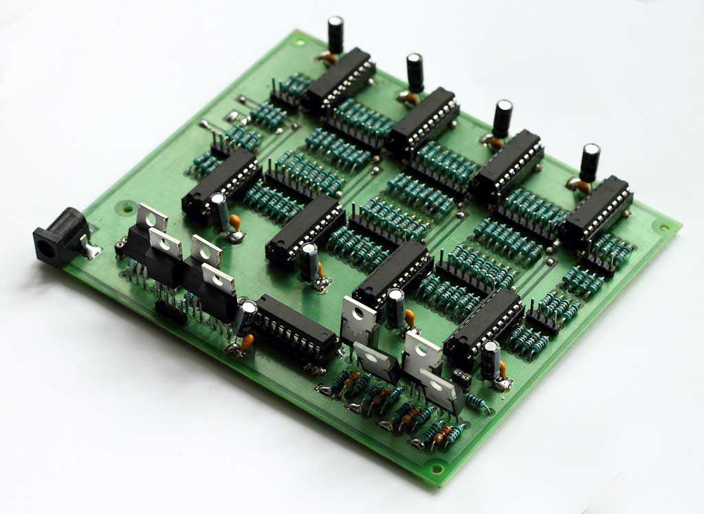
Driving circuit PCB
To make building the driving circuit easier, I have designed a printed circuit board to hold all the components. The board, which is 140*120 mm in size, has all the right connections and can safely be used to create the driver circuit for an LED cube of N*N*N, where N<=8. Of course, it’s possible to build the driving circuit on prototyping boards or with some other methods, but this printed circuit is a much cleaner and safer solution, with no ugly wires hanging around.
For more detail: Building an 8x8x8 LED Cube – The Driving Circuit