The AAA Robot is a perfect robot for beginners. It is versatile, easy to build, and discusses many of the topics roboticists need to learn, including but no limited to transistor switches, motor driving nad analog sensors. This Instructable includes step-by-step instructions on how to build your very own robot.
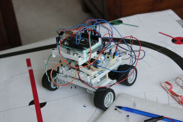
This robot has two modes, manual and automatic. In manual mode, one pair of sensors is compared on the left and right side of the robot and the code (attached in file) will compare the two readings and steer the robot towards the stronger reading. The automatic mode pretty much does the same, except you can switch between three sensors, using one at a time.
To build this robot you will need:
– LM 272 Op Amp
– Resistors (3)
* 1k Ohm (2)
* 470 Ohm
– 2N3904 NPN Transistors (2)
– 2N3906 PNP Transistors (3)
– Arduino Uno
– 9 Volt Battery
– 1n4148 Diodes (2)
– 5.6 nF Capacitors (2)
– Wires (approx 10 ft)
– Electrical tools (i.e.- soldering irons, wire clippers, etc.)
– DC Motors (2)
– Arduino Power Cable
When you have all your stuff ready, get your safety goggles and start building!
Step 1: Inserting the chip
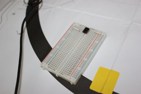
Insert the LM 272 Op Amp with pin 1 on e1 on the breadboard. Then connect pin 4 to ground and pin 8 to voltage. RECALL THAT ALL TIE POINTS ON THE BREADBOARD IN THE SAME ROW ON THE SAME SIDE OF THE CHIP SLOT ARE CONNECTED.
Step 2: Comparator Circuit
Insert a 1k resistor from pin 2 of the 272 to ground and another 1k resistor from pin 6 on the 272 to ground. Connect pin 2 to b5 and pin 6 to d5. Then connect pin 5 to i5 and pin 2 to g5.
Now we’ll hook up the outputs to the Arduino. Connect pin 1 of the 272 to pin 6 on the Arduino and pin 7 on the 272 to pin 7 on the Arduino.
After the comparator wiring iss finished, we can proceed to sensor triggering and transistor switches.
Step 3: RGB LED Hookup and Transistor Switches
First insert an RGB LED with the cathode at c14, red at c13, blue at c16 and green at c15. Place the 470 Ohm resistor across a14 and ground. This resistor will prevent the LED from drawing excessive current while giving it a nice glow.
Now that the LED is safely wired, we can start adding the transistor switches to power the leads and sensors. Since the comparator compares two voltages, we don’t have to worry about the number of sources we hook up to the transistors. Insert one transistor with E at g12, B at g11, and C at g10. Connect the E pin to voltage. Connect C on the transistor to the red lead of the LED and to h18. Then, with jumpers, connect B to pin 8 on the Arduino. Insert the second transistor with E at h12, B at h13, and C at h14. Connect C to the green lead on the LED and h19. Using jumpers again, connect B to pin 9 on the Arduino. Insert the third transistor with E at h17, B at h16 and C at h15. Connect E to voltage and B to pin 12 on the Arduino, once again, using jumpers. Finally, connect C to the blue lead on the RGB and to h120.
The transistor switches and RGB LED are now done. Make sure your wiring is correct and that you are using PNP transistors.
Step 4: Motor Drivers
Now we’ll build the motor drivers. In order to supply the DC motors we’ll be using, we’ll need to rectify the current and use a capacitor to hold the extra charge.
Take 1 5.6 nF capacitor and place it across a30 and a 26. Then place the other 5.6 nF capacitor and place it from j30 to j26. These Capacitors will hold the charge generated by the motor spinning.
Then place one diode (anode to cathode) from e30 to e26. Place the second diode from f30 to f26, once again, anode to cathode. These diodes will rectify the current supplying the motor.
For more detail: AAA Robot (Autonomous Analog Arduino)