When making videos with a tripod fluid head, there aren’t that many movements you can do. You’ve got tilt and pan – so basically either a vertical movement or a horizontal movement.
Both of these have one common characteristic: the camera stays in pretty much the same space for the whole movement, meaning you can’t get any parallax movement (parallax is basically what occurs when you drive on the road and look on the side: near objects seem to move differently than the objects that are further).
To make that kind of movement possible, the cinema industry uses dollies or sliders. And luckily for us, in the modern-day and age, these kind of tools have become very affordable also for amateur filmmakers. 😀
I found this basic slider from Amazon for 40€ – that’s a bargain considering the rails are made out of carbon fiber and the other pieces are aluminum. The build quality is top-notch and there was no way I could have made anything even closely as efficient with the tools and resources I have – that’s why I decided to go the buy route instead of the DIY for the slider part.
However, there is one incredibly useful feature that this slider doesn’t have and that is motorization. You see, when you slide your camera on the rails by hand, there are small inconsistencies in the movement, that make the video look less professional than it could have been when you had used a motor to move the camera. Also, with motorization, you can make time-lapses over multiple hours with a very clean and smooth movement.
That’s why I decided to upgrade my slider with and Arduino controlled stepper motor, while also making the slider portable using common Sony NPF style batteries to be able to take the slider in nature or on travel.
Supplies
Basic camera slider
Arduino nano
NEMA 17 stepper motor
Aluminium enclosure
Nema 17 vibration dampner
A4988 or TMC2208 (better) motor driver
NPF battery charger
Timing Belt and 2 pulleys
1 red LED
Wires
Heat shrink tubing and electrician tape
1/4 inch to 3/8 inch adapter
10K potentiometer
3 position toggle switch
On/Off switch
2 End stops
Step 1: Watch the Video
If you don’t want to read through the whole article to see the project, that’s fine. Here’s a video of me making the slider so you can feel the same feeling of accomplishment that I did when I finished the slider, although you’ll get it with 4 minutes instead of a month.
Also, if by any chance you speak French, here’s a full tutorial on the project en français: https://www.youtube.com/watch?v=nK_Dmr8oF9s&ab_channel=UrsusDiscursus
Step 2: Build the Circuit
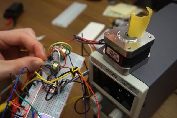
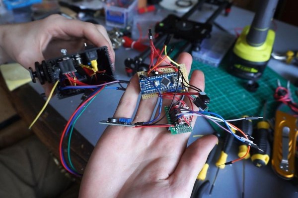
First, gather all the components and build the circuit on a breadboard. This allows you to check if all the components work as they should without soldering anything. Also, it will be easier for you to make the final soldering if you already have laid everything out correctly on the breadboard.
Make sure to plug the right pins on the Arduino to the right components, as the Arduino code will not otherwise work as it should.
Step 3: Making It Cordless
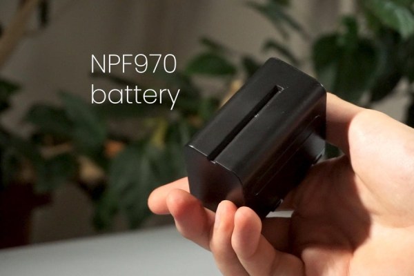
The NPF batteries are the most common batteries used in the amateur film industry. Most LED panels and camera monitors use them, so I decided to make my slider also compatible with NPFs.
To do that, I disassembled a cheap battery charger to recover the connector plate with the positive and negative terminals. I’m not sure if the NPFs have an over-discharge protection built-in or not, but I haven’t got any problems so far.
Step 4: The CODE
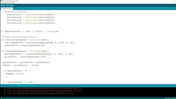
I wanted my slider to be able to make time-lapses but also normal speed videos. That means, that the range of different speeds the motor can be set to needs to be very large.
I wanted to make initially a super polished system with an OLED screen and a rotary encoder to be able to either set the speed of the motor or the time it would take the camera to go from one end of the slider to the other. However, after a week of trial and error, I found out that the library needed to run the OLED screen can’t work at the same time that the library for the stepper motor. So, I decided to go screenless and incorporate a very old-school system to control the motor speed:
One potentiometer controls the Coarse speed. When it’s set to zero, nothing happens and when it’s set to maximum, the slider will move at almost the maximum rate.
The other potentiometer controls the Fine speed. Using that, you can make long time-lapses over several hours, depending on how far you turn the potentiometer.
The two potentiometers add up to make one single speed value – so by combining them you can quickly fine-tune the speed of your slider to the exact speed you want. And yes, I did rip off that system from basic variable bench power supplies but hey – it’s simple and it works perfectly for this situation 🙂
Here the Arduino code: https://github.com/DiscursusYT/Ursus
Step 5: The Limit Switches
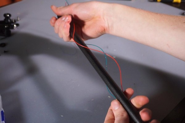
To prevent the camera from crashing in the side of the slider, I set up small limit switches that tell the Arduino to reverse the motor direction. I passed the wires through the carbon fiber tubes and made a connector with breadboard cables to be able to plug it in and out of the main circuit.
It was a lot of hustle and I wouldn’t bother doing that system again if I had to redo the project. It also ruined the slider for when I want to use it without the motor assembly, as the limit switches are screwed into the aluminum and will leave ugly holes when removed.
A lot cleaner solution would have been the use of sensorless homing – a technology that senses lost steps in the motor when the carriage hits a limit to know that it’s time to reverse the speed and come back. It would have required more coding, but at least the slider would still look like new.
Also, passing the cables through the rails was not worth it in my opinion – if you plan to use limit switches, just tape the cables on the rails with gaffer tape.
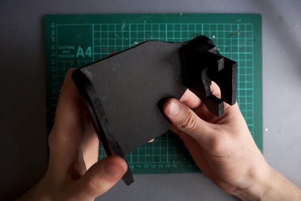
Step 6: The Box

To give the slider a visually more appealing appearance, I decided to use a black aluminum enclosure. Not only does it look sleek, it’s also easier to work with and to clean.
For starters, I placed all the components on the enclosure and measured how much space each of them needs. Then, I used a hole punch to mark the location of the holes to prevent the drill bits from ice skating on the anodized surface.
For the drilling, use a small drill bit first, then, go larger and larger until you have a hole that fits the component. There are also step drill bits’ that allow you to make pretty large holes in one go, using a single bit for added convenience.
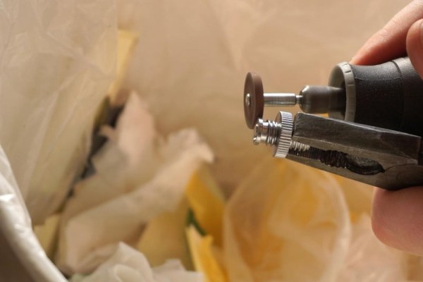
To make the rectangular hole for the switch, I used a Dremel tool with a metal cutting blade.
Step 7: Connecting the Box With the Slider
To mount the box to the slider, I used a combination of different camera thread adaptors. I ground down the edge of a female adaptor so that it blocks itself against the wall inside the aluminium enclosure. This structure does work, but it’s a bit flimsy, that’s why I’ll add later a bracket made out of MDF to keep everything in place.
Step 8: Mounting Everything
To make it easier to populate the box, I separated the circuit into chunks that would connect together with breadboard connectors. That allowed me to mount every component by itself, and only, in the end, add the main circuit (- because as I always, I wanted to make everything as small and compact as possible, thus wasting a lot of time replacing the components I accidentally damaged by pressing them together during the assembly).
To make life easier for you, use a bigger enclosure or one that separates into two halves, to have better access to the components.
To mount the NPF battery mount, I drilled holes in the top plate so that the hot glue has something to hold onto.
Once all the components are in place, test the circuit to see if everything works. Only then, put on the caps for the potentiometers, as they are a nightmare to take off.
Step 9: The Timing Belt
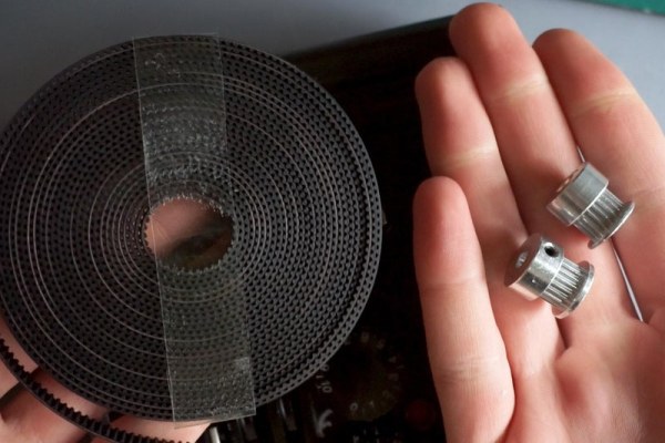
To move the camera carriage, I set up a timing belt that goes from the motor pulley to a smooth metal tube squashed between two washers to keep everything on the right track. The carriage was then equipped with another camera thread adaptor to connect it to the timing belt and make it move.
Step 10: Improving the Mounting System
As I mentioned before, the camera adaptor system wasn’t strong enough to my taste – that’s why I made a connector out of MDF, that attaches the controller box to the slider for added support. Now, I don’t have to worry about the connector snapping when travelling – even though it’s still not perfect and I’m sure there’s still lots of room for improvements. But I’m still happy with how it turned out.
Source: How to Motorize a Camera Slider (Battery Powered)