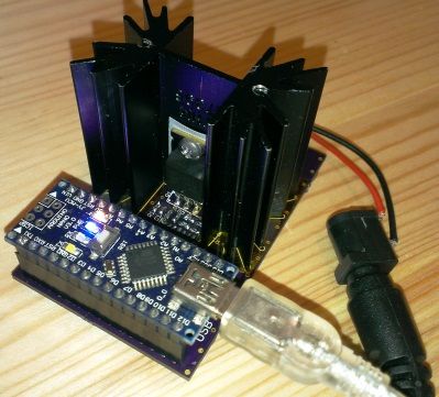
Summary: I designed an electric load. Using an Arduino Nano, the load can be programmed, and the voltage and current are measured. You can set a constant current (CC), a constant power (CP), or a constant resistance (CR) load by simply typing it in to the Arduino Serial Monitor. The circuit is designed for up to 30V, 5A, and 15W. An opamp, a mosfet, and a small sense resistor form the constant current circuit. The current is set using a DAC. Two other opamps measure the power supply voltage and the current. The circuit is powered from the Arduino USB voltage. I reflow soldered the board using the hacked toaster oven at the hackerdojo. Here are pictures of the reflow soldering process.
Hardware
- Custom designed PCB ($23)
- Arduino Nano board ($12)
- 2x 15pins 0.1″ pitch female header connectors ($2)
- AD8608 Rail-to-rail opamps ($3)
- MCP4725 DAC ($3)
- IRLZ44Z N-channel MOSFET ($2)
- SK 129 38mm Heat sink ($1)
- 0603 resistors and capacitors ($2)
- screw terminal ($1)
I chose to use an Arduino Nano board because it is small, cheap, easily interchangeable, it has a power supply that can be used to supply other circuits, and it can easily be programmed with the Arduino IDE. The Arduino is placed on female header connectors on the board. I chose to use the same DAC as on Adafruit and Sparkfun DAC breakout boards. The DAC can be supplied from 5V and the the output voltage is rail-to-rail. A description for using the MCP4725 DAC and library with Arduino can be found here on the Adafruit website. The DAC connects to the Arduino using I2C.
Opamp ICD1, mosfet Q1, and the 0.1 Ohm sense resistor form the constant current circuit. I chose the AD8608 opamp because it is a quad opamp, it can be supplied from 5V, and it has rail-to-rail voltage output. The mosfet functions as a voltage dependent resistance, and in the linear range. I chose a popular and widely available mosfet with a gate threshold voltage between 2.5 and 3V for currents up to 5A. I found the heat sink in a local electronics shop for $1. The mosfet, the heatsink, and their interface, have a combined thermal resistance of about 9 degrees Celsius per Watt. The maximum operation temperature of the mosfet is 175 degrees Celsius. This means that, at 25 degrees Celsius ambient temperature, maximal 15 Watt can be dissipated without active cooling.
To set a current of 1A, the DAC must output 1V. This voltage is divided by 10 using voltage divider R6 and R7 and this 0.1V is applied to the plus input of the opamp. The opamps adjusts it output voltage until it measures the same potential on it minus input, the feedback voltage from the sense resistor. That’s the case when a current of 1A runs through the 0.1 Ohm sense resistor. The capacitor (C4) value in the RC filter may be changed to a suitable cut off frequency, or left out. R5 and C1 are designed to prevent the opamp from oscillating, and the values were taken from a proven design.
For more detail: Arduino based programmable load