Hello friends, I hope all are fine and having fun with your projects. Today, I am going to share a very Simple Arduino LED Example in Proteus ISIS. I have designed a very basic example in Proteus in which I am going to blink single LED first using Arduino and then I am going to blink multiple LEDs in Proteus.
When you start working on Arduino then Arduino LED example is the first example which you must try because its the easiest one. Moreover, we all know that we have a small LED connected to pin # 13 on each Arduino so you can also check your Arduino as well that whether its working or not. So, let’s get started with Simple Arduino LED Example in Proteus ISIS:
A Simple Arduino LED Example in Proteus
- You can download, all the simulation files and codes for Arduino LED examples used in this tutorial, by clicking the below button:
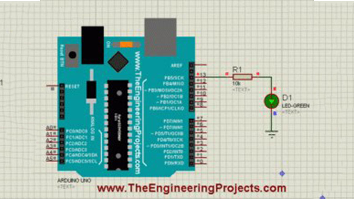
First of all, design a simple circuit of Arduino LED in Proteus ISIS as shown in below figure:
- Now as you can see in the above figure that I have used an LED on Pin # 13 of Arduino UNO.
- So, now upload the below sketch in your Arduino, its the Blink Example from Arduino, which works perfect for this Arduino LED Example:
1 2 3 4 5 6 7 8 9 10 11 | void setup() { pinMode(13, OUTPUT); } // the loop function runs over and over again forever void loop() { digitalWrite(13, HIGH); // turn the LED on (HIGH is the voltage level) delay(1000); // wait for a second digitalWrite(13, LOW); // turn the LED off by making the voltage LOW delay(1000); // wait for a second } |
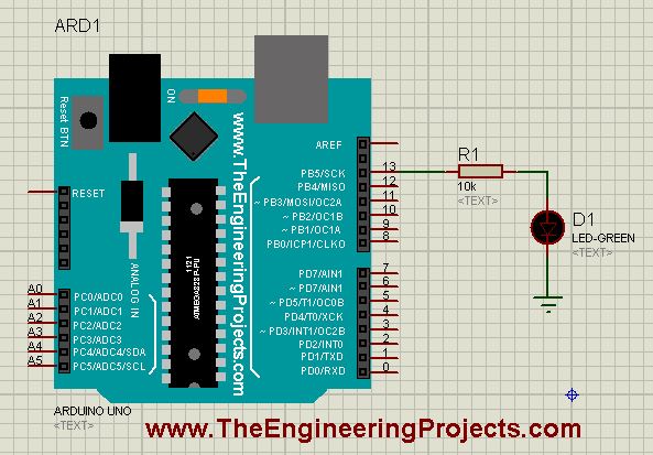
- Once the hex file is uploaded in the Arduino then run your Arduino LED Proteus Simulation and if everything goes fine then your LED will start blinking as shown in below figure:
- Now you can see in the above figure that our LED at Pin # 13 started blinking.
- If you read the above code of Arduino LED exmaple then its quite simple, first of all I just make the Pin # 13 output and then I have made it HIGH and LOW with a delay of 1000 msec.
- You might wanna read How to use digitalRead in Arduino that will give you a better idea of How to deal with any digital pin.
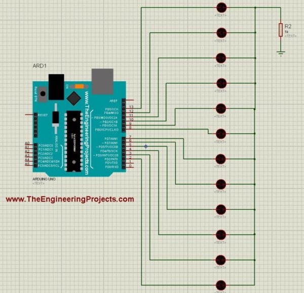
- So, now let’s add more LEDs on other digital Pins of Arduino.
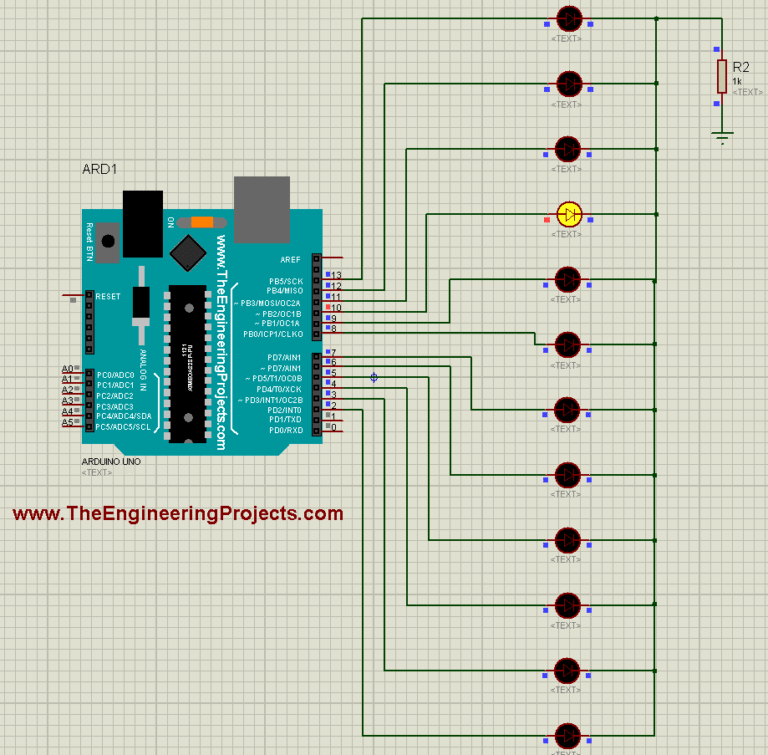
- So, design a simulation as shown in the below figure:
- Now compile the below code in your Arduino software and Get your Arduino Hex file:
1 2 3 4 5 6 7 8 9 10 11 12 13 14 15 16 17 18 19 20 21 22 23 24 25 26 27 28 29 30 31 32 33 34 35 36 37 38 39 40 41 42 43 44 45 46 47 48 49 50 51 52 53 54 55 56 57 58 59 60 61 62 63 64 65 66 67 68 69 70 71 72 73 74 75 76 77 78 79 80 81 82 83 84 85 86 87 88 89 90 91 92 93 94 95 96 97 98 99 100 101 102 103 104 105 106 107 108 109 110 111 112 113 114 115 116 117 118 119 120 121 122 123 124 125 126 127 128 129 130 131 132 133 134 135 136 137 138 139 140 141 142 143 144 145 146 147 148 149 150 151 152 153 154 155 156 157 158 159 160 161 162 163 164 165 166 167 168 169 170 171 172 173 174 175 176 177 178 179 180 181 182 183 184 185 186 187 188 189 190 191 192 193 194 195 196 197 198 199 | int Led1 = 13; int Led2 = 12; int Led3 = 11; int Led4 = 10; int Led5 = 9; int Led6 = 8; int Led7 = 7; int Led8 = 6; int Led9 = 5; int Leda = 4; int Ledb = 3; int Ledc = 2; void setup() { pinMode(Led1, OUTPUT); pinMode(Led2, OUTPUT); pinMode(Led3, OUTPUT); pinMode(Led4, OUTPUT); pinMode(Led5, OUTPUT); pinMode(Led6, OUTPUT); pinMode(Led7, OUTPUT); pinMode(Led8, OUTPUT); pinMode(Led9, OUTPUT); pinMode(Leda, OUTPUT); pinMode(Ledb, OUTPUT); pinMode(Ledc, OUTPUT); } void loop() { digitalWrite(Led1, HIGH); digitalWrite(Led2, LOW); digitalWrite(Led3, LOW); digitalWrite(Led4, LOW); digitalWrite(Led5, LOW); digitalWrite(Led6, LOW); digitalWrite(Led7, LOW); digitalWrite(Led8, LOW); digitalWrite(Led9, LOW); digitalWrite(Leda, LOW); digitalWrite(Ledb, LOW); digitalWrite(Ledc, LOW); delay(1000); digitalWrite(Led1, LOW); digitalWrite(Led2, HIGH); digitalWrite(Led3, LOW); digitalWrite(Led4, LOW); digitalWrite(Led5, LOW); digitalWrite(Led6, LOW); digitalWrite(Led7, LOW); digitalWrite(Led8, LOW); digitalWrite(Led9, LOW); digitalWrite(Leda, LOW); digitalWrite(Ledb, LOW); digitalWrite(Ledc, LOW); delay(1000); digitalWrite(Led1, LOW); digitalWrite(Led2, LOW); digitalWrite(Led3, HIGH); digitalWrite(Led4, LOW); digitalWrite(Led5, LOW); digitalWrite(Led6, LOW); digitalWrite(Led7, LOW); digitalWrite(Led8, LOW); digitalWrite(Led9, LOW); digitalWrite(Leda, LOW); digitalWrite(Ledb, LOW); digitalWrite(Ledc, LOW); delay(1000); digitalWrite(Led1, LOW); digitalWrite(Led2, LOW); digitalWrite(Led3, LOW); digitalWrite(Led4, HIGH); digitalWrite(Led5, LOW); digitalWrite(Led6, LOW); digitalWrite(Led7, LOW); digitalWrite(Led8, LOW); digitalWrite(Led9, LOW); digitalWrite(Leda, LOW); digitalWrite(Ledb, LOW); digitalWrite(Ledc, LOW); delay(1000); digitalWrite(Led1, LOW); digitalWrite(Led2, LOW); digitalWrite(Led3, LOW); digitalWrite(Led4, LOW); digitalWrite(Led5, HIGH); digitalWrite(Led6, LOW); digitalWrite(Led7, LOW); digitalWrite(Led8, LOW); digitalWrite(Led9, LOW); digitalWrite(Leda, LOW); digitalWrite(Ledb, LOW); digitalWrite(Ledc, LOW); delay(1000); digitalWrite(Led1, LOW); digitalWrite(Led2, LOW); digitalWrite(Led3, LOW); digitalWrite(Led4, LOW); digitalWrite(Led5, LOW); digitalWrite(Led6, HIGH); digitalWrite(Led7, LOW); digitalWrite(Led8, LOW); digitalWrite(Led9, LOW); digitalWrite(Leda, LOW); digitalWrite(Ledb, LOW); digitalWrite(Ledc, LOW); delay(1000); digitalWrite(Led1, LOW); digitalWrite(Led2, LOW); digitalWrite(Led3, LOW); digitalWrite(Led4, LOW); digitalWrite(Led5, LOW); digitalWrite(Led6, LOW); digitalWrite(Led7, HIGH); digitalWrite(Led8, LOW); digitalWrite(Led9, LOW); digitalWrite(Leda, LOW); digitalWrite(Ledb, LOW); digitalWrite(Ledc, LOW); delay(1000); digitalWrite(Led1, LOW); digitalWrite(Led2, LOW); digitalWrite(Led3, LOW); digitalWrite(Led4, LOW); digitalWrite(Led5, LOW); digitalWrite(Led6, LOW); digitalWrite(Led7, LOW); digitalWrite(Led8, HIGH); digitalWrite(Led9, LOW); digitalWrite(Leda, LOW); digitalWrite(Ledb, LOW); digitalWrite(Ledc, LOW); delay(1000); digitalWrite(Led1, LOW); digitalWrite(Led2, LOW); digitalWrite(Led3, LOW); digitalWrite(Led4, LOW); digitalWrite(Led5, LOW); digitalWrite(Led6, LOW); digitalWrite(Led7, LOW); digitalWrite(Led8, LOW); digitalWrite(Led9, HIGH); digitalWrite(Leda, LOW); digitalWrite(Ledb, LOW); digitalWrite(Ledc, LOW); delay(1000); digitalWrite(Led1, LOW); digitalWrite(Led2, LOW); digitalWrite(Led3, LOW); digitalWrite(Led4, LOW); digitalWrite(Led5, LOW); digitalWrite(Led6, LOW); digitalWrite(Led7, LOW); digitalWrite(Led8, LOW); digitalWrite(Led9, LOW); digitalWrite(Leda, HIGH); digitalWrite(Ledb, LOW); digitalWrite(Ledc, LOW); delay(1000); digitalWrite(Led1, LOW); digitalWrite(Led2, LOW); digitalWrite(Led3, LOW); digitalWrite(Led4, LOW); digitalWrite(Led5, LOW); digitalWrite(Led6, LOW); digitalWrite(Led7, LOW); digitalWrite(Led8, LOW); digitalWrite(Led9, LOW); digitalWrite(Leda, LOW); digitalWrite(Ledb, HIGH); digitalWrite(Ledc, LOW); delay(1000); digitalWrite(Led1, LOW); digitalWrite(Led2, LOW); digitalWrite(Led3, LOW); digitalWrite(Led4, LOW); digitalWrite(Led5, LOW); digitalWrite(Led6, LOW); digitalWrite(Led7, LOW); digitalWrite(Led8, LOW); digitalWrite(Led9, LOW); digitalWrite(Leda, LOW); digitalWrite(Ledb, LOW); digitalWrite(Ledc, HIGH); delay(1000); } |
- Upload this hex file in your Proteus Arduino and then run your simulation.
- If everything goes fine then you will get all your LEDs blinking.
- I have shown a glimpse of its working in below figure:
- So, download the files and run your simulation and test it out.
- If you check the code then it seems quite lengthy but its very simple.
- I am just keeping one LED on and others OFF.
- Now, let me tell you one thing, this is the the best way of coding but for starters you should first try it out.
- In the coming lecture, I will teach you How to write Arduino Code Efficiently like I don’t wanna add 100 lines just for such small work.
- So, hopefully tomorrow I will teach you How to write small but efficient Arduino codes and will add the link here.
So, that’s all for today. I hope you have enjoyed today’s Arduino LED Example and are gonna test it. So, see you in next tutorial. Take care !!! ?