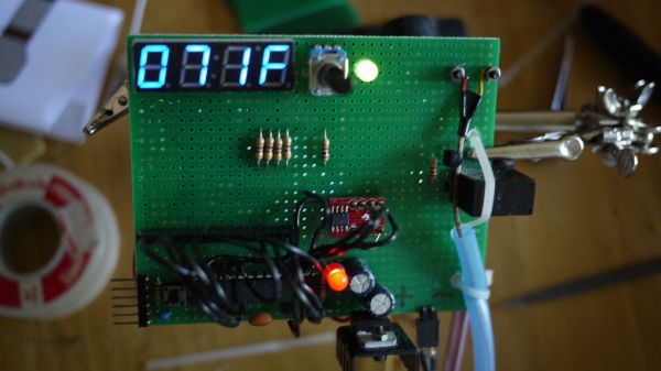
This project will show you how you can create your own programmable thermostat with temperature probe, an LED readout and ability to remote control outlets.
The core of this project is actually a driver for a 4 digit seven segment display.
There are lots uses for such a device. You can purchase something called a PID controller for about $120. The parts for this cost me about $66. If you can scrounge some of the parts you can do even better.
I use mine to control hot water baths for cooking meet. See my instructable on cooking perfect steak for why you might want this.
There are probably a dozen ways to do this. This was my way.
This project requires soldering small surface mount components (well one easy one IMHO). There are a lot of wires and it can be hard to debug certian problems. This is probably not a great project for a novice or the easily frustrated.
At this time the instructable isn’t as detailed and foolproof as possible. My prototype works and this is my attempt to document the process. However, until I build my sweet new steampunk themed version, the instructable is going to be a little bit raw. You should be confident about these sorts of projects enough to do some minor debugging of the hardware and connections before you dive in. Just in case I got something wrong, you know. The software is solid at least. 🙂
Recomended Instructables:
Replace the $20 arduino in this project with $8 worth of electronics.
Generic Micro Controller switch outlets. I embedded this idea into this project. You can just build this stand alone version on hook it up to this project.
UPDATE: 2011-July-28 LM335A sensor version, cheaper, no surface mount soldering.
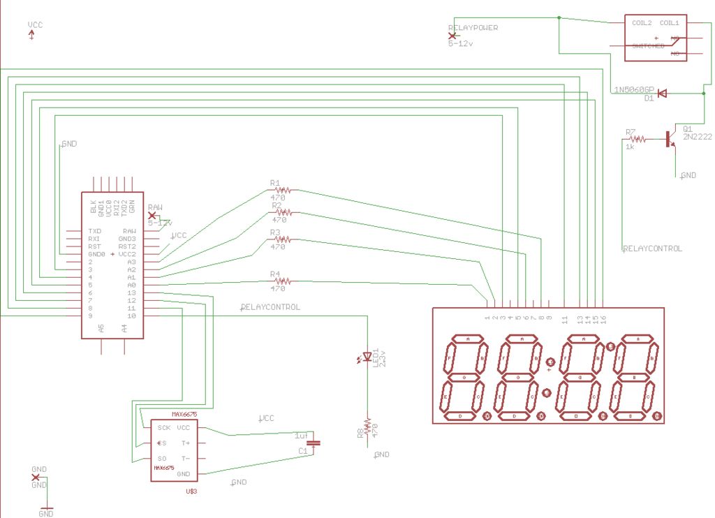
I am experimenting with replacing the thermocouple and booster with an LM335A sensor. It’s not as accurate, and it won’t go above 100 degrees C. However it’s $1.50 compared to $28 for the thermocouple and booster. For souse-vide cooking it should work fine. There is a PCB123 diagram file in the diagram step if you want to see how to hook one up.
I have also gone to using the Atmega168 chip directly with the minimum hardware needed to support and program it. That’s also in the PCB123 file along with a circuit board.
I plan to have circuit boards and solder your own kits available on Kickstarter soon. I am planning a run of 500. The kits will be ~$40 shipped. Let me know if you are interested. The Kickstarter never happened. I did another couple Arduino based Kickstarters and documented the projects on Instructables. Stay tuned, more to come I am sure.
Step 1: Gather Materials
Project:
1 X Arduino Pro Mini 328 – 5V/16MHz
1 X Thermocouple Type-K Glass Braid Insulated
1 X Thermocouple Amplifier Digital MAX6675
1 X Wall Adapter Power Supply – 5VDC 1A
1 X Outlet from the home store
1 X SOIC to DIP Adapter 8-Pin
1 X 4-Digit 7-Segment Display
1 X plastic outlet box
1 X extension cord or old computer cord.
1 X Relay SPDT Sealed 5v coil T9AS5D12-5
1 X Rotary Potentiometer – Linear COM-09288
1 X Trim potentiometer (optional)
1 X 2n2222 transistor or other similar switching PNP resistor.
1 X 1uf capacitor
5 X 330 ohm resistor (This used to say 470, but that makes the display pretty dim)
1 X 1N4148 diode
4 ft X Aquarium tubing (the bluish kind that might be silicone)
1 X breadboard, perfboard, circuit board or custom enclosure.
Spring Terminals – PCB Mount (2-Pin) (sparkfun PRT-08073)
Various wire.
Pins for mounting the Arduino. I used the legs off resistors and so on from previous projects, but you can buy some headers.
Coming Soon:
I am prototyping circuit boards for these. I got my first one from BatchPCB not long ago and it worked, but needs some changes to be ready for prime time. Hopefully boards with instructions will be done by end of summer 2011. BatchPCB sure is slow. 🙂
Gear:
- Soldering Iron. (Adjustable is highly recomended)
- Soldering supplies.
- Basic soldering skills or a willingness to buy replacement parts as you learn. Soldering the Max chip is the hardest part of the project. It’s not too hard to solder to the breakout board. Check out these videos and explanation. http://www.sparkfun.com/tutorials/96
- FTDI basic breakout or other way to interface with your Arduino chip.
- Computer to program the chip from.
You can use any kind of Arduino you want. If you get the mini like I did, make sure you have the programming chip or cable. You can also get or make an RBB arduino to shave a few dollars off the project. If you are really ambitious you can hack together an Arduino from an Atmeta chips and parts.
You can find everything electronic at Sparkfun.com. Of course you can shave some cost by sourcing some stuff elsewhere. For example, if you can find a wall adapter in the 5v range at the dollar store or second hand. Etc.
Note that the program I have later works with a button control and not a potentiometer. I will update this soon.
Step 2: Test the components.
Before you solder this all up, it’s a good idea to get it working on a bread board. So, go to the next step, but do it once without soldering on your breadboard.
Once you get connections working, you can start soldering them together.
You can modify the program easily to to cycle through different displays. Don’t just use 8888 since you might short some wires and not realize it. Each possible segment has an entry in the segments array, you can cycle through them and each digit to get a good test program going. Try replacing loop with this to get a program that will light each segment in turn.
int _digit = 0;
int _segment = 0;
void loop(){
_segment++;
if(_segment > 7) {_segment = 0; _digit++;}
if(_digit > 3) {_digit = 0;}
delay(500);
lightDigit(digit[_digit], segments[_segment]);
//readTemp();
//handleButton();
}
1 X Thermocouple Type-K Glass Braid Insulated
1 X Thermocouple Amplifier Digital MAX6675
For more detail: Make your own programmable thermostat for $66 with Arduino