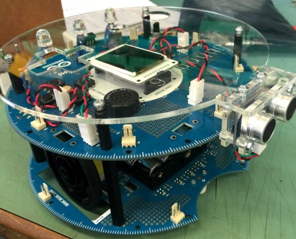
Designing a custom plate for the Arduino Robot, adding jumbo LEDs and displaying readings from an ultrasonic distance sensor to the LCD.
My previous post on the Arduino Robot described how I took the Runaway Robot sketch and modified it work with the PING ultrasonic distance sensor. This post is still based around the same example sketch, however the code was not only further modified but additional components were connected to the control board, and a custom acrylic top plate was designed and laser cut to mount these.
Design brief
After having got the PING sensor to work with Runaway Robot I wanted to add some new features:
LEDs to indicate when the robot was free to move or if it was blocked.
Using the LCD on the control board to display distance values obtained from the PING.
Custom top plate to mount the LEDs and PING sensor, so that it is aesthetically pleasing and robust.
Where to start?
I decided rather than attempt to add all the features at once it would be wise to add each one a step at a time. This meant that if there happened to be and issue it would be much easier to determine where the problem was rather than having to start all over again.
The housing for the robot had to be left until last, when all the components were added. So it was a case of deciding to tackle the LEDs first or the LCD. Since the LCD just involved modifying code I though it might be fun to start by adding the LEDs.
Jumbo LEDs
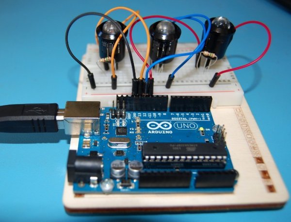
I wanted the LEDs to stand out and so I ordered some 10mm LEDs instead of the more common 5mm. As I hadn’t used these ones before I wanted to test them before adding them to the robot. To test the LEDs I used a breadboard to connect them to an Arduino Uno and checked the LED manufacturer data sheet to calculate the correct size resistors(I used 150Ω).
As the LEDs worked fine with the Uno I was confident about adding them to the Arduino Robot. First I had to find the remaining unused digital pins. When I found which digital headers were available I decided which three of these to use, and soldered on a three pin header to each. This was so the LEDs could be removed if the pins were needed in another project, instead of soldering the LEDs straight into the control board.
Read More: Johnny 6 is alive!