This project details a Flowcode and E-blocks based weather station capable of reading local temperature and humidity with 2 remote thermo-hygrometer sensors. The local board also incorporates a real time clock. This article has been contributed by Flowcode user John Crow.
Flowcode can be downloaded and trialled for free at the Matrix Technology Solutions website. You can also purchase Flowcode licences through the RS website.
Introduction.
Flowcode V7 has (along with many other new features) a macro to use the nRF24L01 2.4 GHz RF Transceiver.
It was this component that inspired me to develop this project.
I should point out this project is only compatible with Flowcode 7 as the nRF24L01 component is not included in earlier versions.
Also the component is used under the ISM (industrial Scientific and Medical Licence) and can be used freely for experimentation without the need to obtain a formal licence.
The board may suffer from interference from microwave ovens as they are on a similar frequency.
The project assumes the user is familiar with the basic use of Flowcode and E-Blocks.
PART 1 Remote Sensor.
The remote sensors use identical hardware, and the only difference in the program loaded is the value of Sensor_ID, either 1 or 2. This is set in the Flowcode program.
Equipment Required. (Per Sensor)
- EB-006 V9 Multi-programmer (Fitted with 16F1937)
- EB-005 LCD E-Block
- EB-016 Proto-Board
- Power Supply (9V DC)
- nRF24L01 RF Module (With suitable aerial) (Sparkfun)
- HTU21D (SHT21 Sensor) Temperature / Humidity Module (Adafruit)
- Jumper Wires (To connect the E-Blocks power)
The RF and Temperature Sensors can be sourced from several places
I have just named the type I’m using.
RS also supply a Thermo-Hygrometer board using the SHT21 sensor. (EBM016)
Connections.
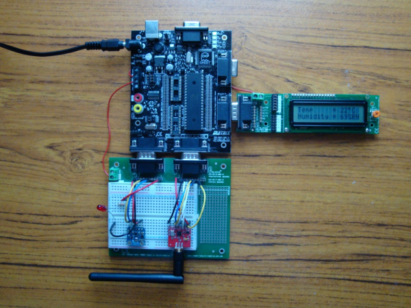
Port B – EB-005 LCD Display.
This gives a local reading of the temperature and humidity data being transmitted.
Both the Thermo-Hygrometer Sensor and the RF Board are plugged into the EB-016 Prototype board, and connected to Ports C & D
Port C – nRF24L01 RF Module.
Hardware Setting Channel 1
- Port C2 CE
- Port C3 SCK
- Port C4 MIOS
- Port C5 MOSI
- Port C7 CSN
- Port D0 Transmit LED Via 330R Resistor to ground.
This module has a 3.3v regulator on board so can be connected directly to the 5V supply from the EB-006.
Cheaper (E-Bay) modules are often only 3.3V so care must be taken when connecting them up.
Port D – HTU210 Thermo-Hygrometer.
This uses the I2C Bus to connect to the microcontroller.
Software setting
- Port D4 SDA
- Port D5 SCL
Power is taken from the 5V supply on the EB-006.
Read More: Developing your own Flowcode 7 controlled weather station