Introduction
Weather-band radio is an awesome public service provided in the US, Canada, and Bermuda. With hundreds of transmitting stations dotting the country, weather radio acts as the “voice of NOAA” (National Oceanic and Atmospheric Administration). In addition to spouting out weather forecasts, weather radio also implements a messaging protocol for emergency weather alerts called SAME (Specific Area Message Encoding).
An audio snippet recorded out of the Si4707. Winter storm advisory in Boulder…at the end of April!
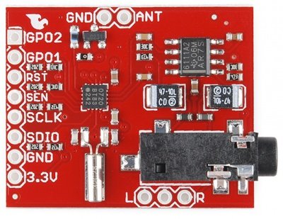
The Silicon Labs Si4707 is capable of both receiving weather radio broadcasts and decoding SAME messages. It’s also able to check for 1050Hz alert tones. It’s a unique chip, and we liked it so much we stuck it on a breakout board. In addition to the Si4707, the breakout also includes supporting passive components and a headphone stereo amplifier.
There are a variety of consumer-grade radio receivers with weather band capabilities built-in. But what’s the fun in that? With the Si4707 you can make your own weather watching radio!
Required Materials
In this tutorial, we’ll explain how to hook-up to the Si4707 breakout using the Arduino development platform. To follow along, you’ll need these materials:
We’ve suggested the RedBoard for all of your Arduino needs, but any of the development boards should work.
You’ll also need a listening device – either headphones or speakers – with a 3.5mm stereo jack connector. You want to hear what the radio has to say, don’t you?!
 Advanced (Optional)
If you’d like to add your own external antenna and/or connect a small speaker to the board, some of these will come in handy:
- A couple feet of wire – This is used to make a really basic antenna.
- Audio speaker – There are a variety of speakers out there including thin and PCB mount packages.
Required Tools
This assembly will require some simple soldering, so you’ll need a soldering iron and a bit of solder.
Advanced (Optional)
If you’re into the more advanced hookup, you’ll need something to cut the jumper on the board. For that, a hobby Knife should be all you need.
Recommended Reading
This tutorial assumes some previous electronics knowledge to get along. If you’re not familiar with these concepts, consider checking out our tutorials on the subject!
- How to Solder – You’ll need some solder points somewhere between the breakout board and your Arduino.
- What is an Arduino? – Be familiar with Arduino. We’ll be talking about it a lot in this tutorial.
- I2C Communication – This is the communication standard the Arduino uses to talk to the Si4707.
- How to Use a Breadboard – This guide will use a breadboard to connect between the Arduino and Si4707 breakout.
- Working With Wire – If you want to add an antenna, you’ll need to cut and strip some wire.
So grab an Arduino and an Si4707 Breakout, follow along, and you’ll be listening to the soothing robotic-weather-person voice in no time!
What’s Weather Band
Weather radio (known as national weather radio or NWR) is a nationwide, 24/7 weather forecasting, watching, and alert system. Weather band transmissions are frequency-modulated (FM) at one of seven VHF frequencies (in MHz): 162.400, 162.425, 162.450, 162.475, 162.500, 162.500, 162.525, or 162.550. With broadcast stations all over the country, upwards of 97% of the U.S. population is covered by NWR.
Click to embiggen this informative map of the many many NWR transmitting stations. (Image courtesy of nws.noaa.gov).
The radio broadcasts usually consist of an automated voice (either Donna, Tom, or Javier) speechifying a weather forecast. They’ll inform you of current temperatures, wind conditions, precipitation, etc., and they’ll give you an outlook for the coming hours and days. The weather-band-radio-robot-voices are really very relaxing, almost hypnotic.
And remember NOAA Weather Radios (very dramatically) SAVE LIVES!!!
What’s SAME?
One particularly critical job of NWR is alerting us to immediate weather emergencies. Those emergency weather alerts are reinforced by Specific Area Message Encoding (SAME). SAME is a digital code transmitted under cover of the normal weather radio audio broadcasts. SAME messages are short, but they convey important information like what weather event triggered the alert (winter storm warning, tornado warning, hurricane, etc.) and the area affected.
The SAME messages are accompanied by a lovely 10 second 1050Hz tone, alerting listeners to the incoming warning message.
The Si4707 is fully capable of interfacing with SAME messages and the 1050 Hz tone. Want the radio to turn on only when an alert is incoming? Or blink an LED when catastrophic weather is headed your way? It’s possible thanks to SAME.
For more information on National Weather Radio head over to NOAA’s homepage.
Board and IC Overview
In the words of Silicon Labs, the Si4707 is “the industry’s first weather band (WB) radio receiver to include a specific area message encoding (SAME) processor.” It’s a really neat chip. Aside from being able to tune to all weather band frequencies and process SAME messages, the Si4707 also hosts a variety of cool features. It’s versatile: it can be interfaced with using either I2C, SPI, or a 3-wire interface. And, it’s got a really clean-sounding audio quality.
Silicon Labs has produced a wealth of supporting material for the chip. All of it hosted on their website. Some of the really useful documents include:
- Si4707-B20 – The datasheet.
- AN332 – The Si4707 programming guide, where you’ll find information about all of the Si4707’s registers and settings.
It’s important to point out that the Si4707 has a maximum interface supply voltage of 3.6V. When we connect it to an Arduino, it’ll be powered by the 3.3V line. Voltage on the input lines should also be limited to about 3.3V as well.
Breakout Board Schematic
The Si4707 Breakout Board surrounds the Si4707 with all of the supporting circuitry one might need to hit the ground running with the chip.
Si4707 Breakout Board schematic. Click to view a larger PDF version.
One of the more important parts surrounding the Si4707 is the 32.768kHz crystal, which provides the IC’s reference clock. All of the I/O lines are pulled up to 3.3V through 4.7kΩ resistors. The antenna portion of the circuit has a filtering 56nH inductor and an ESD protecting diode.
The left and right analog audio outputs of the Si4707 are sent through a headphone amplifier (a TPA6111A2), which boosts the signal. The output of the amplifier is sent to a 3.5mm audio jack.
Board Pin-Out
The Si4707 Breakout has one main interface header and two smaller optional headers on the side of the board.
A view of the bottom of the Si4707 breakout board.
On the main header are the following pins:
- 3.3V – The supply voltage input. This will go to both the VDD and VIO pins of the Si4707. The supply voltage should be between 1.5 and 3.6V.
- GND – This supplies both the digital ground and RF ground of the Si4707.
- SDIO – Serial data input/output for all interfaces.
- SCLK – Serial clock input for all interfaces.
- SEN – Serial enable input. If used in I2C mode, this pin selects the 7-bit address of the IC. In SPI mode, this is the chip-select input.
- RST – The reset input. It’s active-low, so connecting this pin to ground will turn the chip off.
- GPO1 – General purpose output 1.
- GPO2 – General purpose output 2. This pin also serves as an interrupt output if so configured.
Other pins not on the main 8-pin header are:
- ANT – This is connected to the FMI input of the Si4707–the WB RF input. If you’d like to use an external antenna, select this output pin on the jumper (on the bottom of the board, near the pin).
- L and R – These are the analog audio outputs from the headphone amplifier. If you’d rather not use the 3.5mm audio jack, you can use these headers instead.
Well, that explains the board. Now we can move on to hooking it up!
Hardware Hookup
In this section we’ll go from soldering up the Si4707 breakout to wiring it up to your Arduino. After that, on the next page, we’ll get into programming the Arduino to interact with the weather band radio chip.
Soldering Headers
Soldering headers to the Si4707 will create a solid physical and electrical connection to the board. If you’ve never soldered before, don’t worry! We’ve got a tutorial for that. These solder points are among the easier you’ll ever have to make.
After soldering some headers into the breakout board, it should look a little something like this:
Connecting to the Arduino
We’ll be using the Si4707’s I2C interface for communication between the Arduino and Si4707. This interface requires connecting to the SDIO and SCLK pins to send data and a clock signal, respectively. Having control over the Si4707’s reset pin (RST) is also helpful. Aside from that, all we need is 3.3V and ground. Here’s a schematic
Or, for the more visually inclined, a Fritzing diagram:
The SDA and SCL pins should be present on most Arduinos. Older, pre-rev3 Arduinos might not have SCL and SDA pins. In that case, connect SDIO to A4 and SCLK to A5.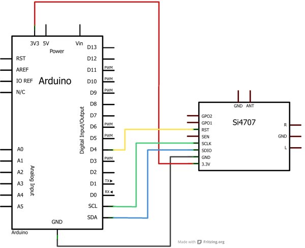
Plug In Headphones/Speakers
No doubt you want to pick up what the weather radio station is putting down! The Si4707 Breakout has an on-board 3.5mm stereo jack, plug some headphones, or your favorite powered speakers, into that jack.
The breakout board comes configured to use the headphone cord as an antenna. So it helps to have headphones or speakers with about 1.5-3ft long, untangled wires.
Once the connections have been made, you can move on to programming the Arduino!
Firmware Upload
Click here to download our Si4707 I2C example code. You can also grab the code from the product’s github repository.
This example code comes with three different files:
- si4707_example_code_i2c.ino – The main Arduino file. This is where
setup()andloop()are defined, as well as a few other global variables and useful functions. Mess with this one as you please. - si4707_system_functions.ino – This is where an array of “system” functions–nitty-gritty functions that create commands, and receive responses–are kept. It should be safe to ignore this file.
- si4707_definitions.h – This file defines all of the Si4707’s register and property addresses. Don’t change these definitions.
Open up si4707_example_code_i2c.ino, and head down to line 62. There’s just one global variable that needs editing before you upload the sketch:
For more detail: Si4707 Hookup Guide