Summary of Make A LED firefly Jars Using Arduino
This project creates fake fireflies in jars using yellow LEDs controlled by an ATtiny45 microcontroller to mimic natural firefly blinking. The circuit uses multiplexing to independently fade four LEDs with only two PWM pins from the microcontroller. The ATtiny45 runs Arduino code with custom timing patterns to make the LED fireflies flash asynchronously, creating a natural random effect. The PCB is single-layer and hand-etched, powered by a 3V coin cell, lasting about three days. This clever design combines simple hardware and programmatic control for an eye-catching decorative effect without real bugs.
Parts used in the LED Firefly Jars Project:
- ATtiny45 microcontroller
- Yellow LEDs (4)
- Coin cell battery (3V)
- PCB (single layer, custom etched)
- IC socket
- Thin wire for LED leads
- Battery holder (for coin cell)
- Jar with lid (for housing the circuit and LEDs)
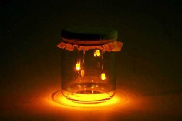
There’s a nice charm to fireflies in a jar—except for, you know, all the dead bugs afterwards. I decided to make a bunch of fake fireflies in real jars for decoration at an outdoor event. The fireflies are yellow LEDs controlled by a small ATtiny45 microcontroller. The control circuit board sits out of sight on the underside of the jar lid and the LEDs hang down on thin wire.
Designing It
I started the project by figuring out the circuit and the code. I prototyped on an Arduino Duemilanove, but my target platform was the ATtiny45 with Arduino bootloader. This meant I had to keep the number of used pins to a minimum and be clever with the code. For the fireflies, I wanted four LEDs fading in and out independently from each other, but the ATtiny45 only has two PWM pins (there could be more PWM outputs—I think—if the second timer is used. I needed the Arduino millis() function though, so I couldn’t repurpose the second timer). How do you fade four LEDs with only two PWM pins? Multiplexing!
By connecting both ends of your LEDs to digitally-controlled outputs (rather than tying one end to Vcc or ground), you can control n*n LEDs with only n+n microcontroller output pins. Some simple math makes it clear that multiplexing works well for lots of LEDs (control 100 LEDs with only 20 pins!), but the utility decreases for small numbers of LEDs (control 4 LEDs with only 4 pins! er, wait…). There are other ways to control lots of LEDs with only a few pins, and if you want to learn more, I recommend a video on multiplexing and a page on charlieplexing, which is a more advanced technique
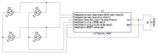
Ok, hang on. Why are you multiplexing only 4 LEDs then? It doesn’t save any pins! That’s right. In this case, multiplexing the LEDs does not save on the number of pins, but it does save on how many of those pins need to be PWM-capable. With a multiplexed grid of 4 LEDs, only 2 pins need to be capable of PWM, because only two LEDs are ever on at a given time. Perfect! The ATtiny has 2 PWM pins. Below is the circuit diagram for my LED fireflies. Four multiplexed LEDs are on the left, the microcontroller is in the center, and a coin cell battery is on the right.
I put the Arduino bootloader on my ATtiny45, which means it can run Arduino code. This was made possible by people way better at this stuff than me, and details on actually using an ATtiny45 with Arduino are over at the MIT high low tech group’s site.
Coding It
Now onto the code. If you want to skip to the good stuff, the source code is at the bottom of the page. I watched too many YouTube videos of fireflies in order to figure out what makes a light look like a firefly. I figured out that if the light quickly fades in, stays lit for a short time, then slowly fades out, firefly-ness is maximized. Then there should be a long pause or wait time before repeating the whole thing. So, I got one LED looking like a firefly, but I wanted four. Not only that, but I wanted each of the four fireflies to have its own independent wait time before turning on again. One LED might turn on every 5 seconds while it’s neighbor turns on every 6 seconds. This way, the fireflies appear to be flashing at random—each individual LED has a very simple and regular pattern, but the entire set of four LEDs won’t repeat a sequence for a very long time. I achieved this (with the help of Katie) by using a running timer and the modulo operation. Basically, at each time step, the program figures out what state each of the four LEDs should be in (off, fading on, fully on, fading off) and sets the appropriate brightness to those LEDs before looping back and doing it again. I also put in some fuzziness into the wait times for each LED. On power up, a random function determines the off time of each LED (within some reasonable bounds), ensuring that no two experiences will be the same!
Making It
I designed the PCB as a single layer board with fairly large through holes, ensuring I would be able to etch the PCB myself. The layout is shown to the right with the battery at the bottom, the microcontroller in the center, and four LEDs around the edges. This is only the second PCB I have etched, but using the toner-transfer method outlined by Alberto and the etching solution posted by The Real Elliot on Instructables, my PCBs came out great!
Once the PCBs were fabricated, I began assembly. There are not that many components, so putting it all together was pretty fast. The only problem was soldering the IC socket. Because of the way I had to mount my PCB, I wanted the traces on the top side.
Unfortunately, that made it hard to solder the legs of the socket. In the end, I was very happy with the LED fireflies. They were instantly recognizable as “fireflies” and looked really nice outside at dusk. Plus, I found out that the small 3V battery will last for about three days! Here are some photos of the assembly process and finished product.
To really experience the LED firefly jar, take a look at the video below. This was an early version, but the basic idea is there. Hopefully a higher-quality video will be coming shortly.
For those interested, here is the code I put on my ATtiny45’s. I don’t promise it’s easy to understand, but take a look if you want!
For more detail: Make A LED firefly Jars Using Arduino