Summary of Arduino Garage Controller
The article describes a custom garage controller project using an Arduino Uno connected via Ethernet to a Vera2 Smart Home Controller. The system automates garage door closing based on real-time schedules, controlled remotely via a smartphone app. It uses two door sensors to detect fully closed and open states and integrates additional relay-controlled functions like irrigation system management. The Ethernet shield provides network connectivity, and relays handle device switching. The Arduino code manages sensor inputs, relay outputs, and communication with the Vera controller. This setup improves convenience and automation beyond prior DIY attempts limited by RTC inaccuracies.
Parts used in the Garage Controller:
- Arduino Uno
- Ethernet Shield compatible with Arduino
- 4 Channel 5 volt relay module
- PC board
- Fuse holder (for 24V irrigation valve power)
- Polarized connector (for 24V supply)
- DB9 male connector with flat ribbon cable
- Miscellaneous screws and bolts
- Plastic enclosure box
- Straight and right angle headers
- Wire-wrap wire
- Magnet wire (for 24V wiring)
- 2 switches with Normally Open (NO) and Normally Closed (NC) contacts
- Speaker or telephone wire (for sensor wiring)
- 2 conductor connectors
Although there are many garage door projects on Instructable using Arduinos, I needed/wanted something different. Last year, we had a warm summer and when I would come home after work, I would leave the garage door open about 1 foot so it could cool off. The trouble was that several nights I left the garage door open overnight 🙁 So I thought, I could use an Arduino with a real-time clock (RTC) to automatically close the garage door at 9 pm. So I built the first version of a garage controller. I used two sensors, one for “door is closed” and the other for “door is fully open” and a relay. The controller worked quite well for the rest of the summer.
When winter came, I decided to unplug the garage controller since I would leave the garage door partially open. This year when it started getting warm again, I plugged in the garage controller again. The trouble was that the RTC was not very accurate and the time was off. The only way to correct the time was to plug my laptop via USB to the garage controller, a pain because I had installed the garage controller on top of the garage door opener. So I had to climb a ladder with my laptop, connect the USB port to the Arduino, upload a “new” sketch that had to correct time and then upload the regular sketch (that didn’t set the RTC).
In the meantime, I had bought a factory refurbished Vera2 “Smart Home Controller” from Mi Casa Verde on eBay. I had also found a Z-Wave home thermostat at Fry’s for $14 so I could automatically set schedules for the heating and air conditioning. The Vera also allows me to remotely control the thermostat from my cell phone using one of the many apps that talk to the Vera.
 Given that I had the Vera (that keeps accurate time) and the fact that you can write your own “plugins” for the Vera, I thought, I should connect my garage controller to the Vera. Once I connected my garage controller, I thought, Hey, I have an Arduino in the garage, what else can I control? So I decided to add more relays to control my irrigation system and replace the timer I have in the garage. Have you ever tried to manually turn on one zone with today’s timers? Now, with my cell phone, I just tap a button!
The garage controller connects to the Vera2 via Ethernet. I’m using an Ethernet shield because they are less expensive than WiFi shields.
I could have used a Raspberry Pi but since its GPIO are 3.3V I decided to stick with the Arduino.
Step 1: Parts & Tools
So here’s are the parts I used:
- Arduino Uno
- An Ethernet Shield (any shield that works with your Arduino)
- A 4 Channel 5 volt relay module
- A PC board
- A fuse holder for the 24V used by the irrigation valves
- A polarized connector for the 24V
- A DB9 male connector with flat ribbon cable (I had laying around)
- Miscellaneous screws and bolts
- A plastic box to hold the controller.
- Various straight and right angle headers
- Wire-wrap wire (I had laying around)
- Magnet wire (for the 24V)
- 2 Switches with NO and NC connections
- Speaker or telephone wire to connect sensors
- 2 conductor connectors
In addition, you’ll need the following tools:
- Soldering Iron
- Solder
- Drill and bits
- Files
- Labeler (optional)
- Arduino Development Software
- A text editor
You also must be familiar with the Vera and how to add your own device to the Vera.
Step 2: Schematic/Block Diagram
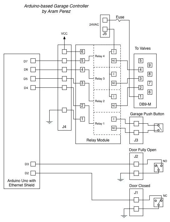
Here’s the schematic/block diagram.
Step 3: Arduino Uno, Ethernet Shield & 4 Channel Relay Module
By trial & error, I first mounted the Arduino Uno to the bottom half of the plastic box by drilling on the bottom. I had to cut and file away the plastic to allow for the USB connector. I used spacers to hold the Arduino Uno to the bottom. In a similar fashion, I attached the 4 channel relay module to the bottom half of the plastic box.
I also drill/cut/filed the holes in the top half of the plastic box for the Ethernet connector, the 24V connector, the DB9 connector and for the sensors and switch headers.
In the first photo below, I’ve already attached the wires from the DB9 connector.
Step 4: Breadboard
The breadboard is what connects the Arduino/Ethernet Shield to the relay module and the “outside” world.
I mounted the 2 switches at each end of the garage door rail. Since I wanted to sense the “normal state” (i.e. the garage door is closed) as HIGH on the Arduino, the closed door sensor is connected to the NO pin and the fully open sensor is connected to the NC pin on the switches.
To open and close the garage door, I then spliced a wire from a relay in the garage controller to the wire coming from the pushbutton on the wall.
Step 6: The Arduino Code
Here’s the code running on the Arduino:
/*
Garage Controller
Written by Aram Perez
Licensed under GPLv2, available at http://www.gnu.org/licenses/gpl-2.0.txt
*/

//#define LOG_SERIAL

#include <SPI.h>
#include <Ethernet.h>
#include <Wire.h>

#define NO_PORTA_PINCHANGES
#define NO_PORTC_PINCHANGES
#include <PinChangeInt.h>

#define IOPORT 23  //Normal telnet port
#define NBR_OF_RELAYS 4

// Garage door sensors & pushbutton
#define GARAGE_CLOSED_SENSOR 2 //Connect to NC terminal, active high
#define GARAGE_PARTIALLY_OPEN_SENSOR 3   //Connect to NO terminal, active high

#define RELAY0 4
#define GARAGE_RELAY RELAY0  //Relay for garage door button
#define RELAY1 5
#define RELAY2 6
#define RELAY3 7

#define CR ((char)13)
#define LF ((char)10)

// Enter a MAC address and IP address for your controller below.
// The IP address will be dependent on your local network.
// gateway and subnet are optional:
static byte mac[] = {
0xDE, 0xAD, 0xBE, 0xEF, 0xFE, 0xED};
static IPAddress ip(192, 168, 1, 170);
static IPAddress gateway(192, 168, 1, 1);
static IPAddress subnet(255, 255, 255, 0);

static EthernetServer server(IOPORT);
static EthernetClient client;

static char relayState[NBR_OF_RELAYS];

class GarageDoor
{bool closedState, partiallyOpenState;
public:
GarageDoor();
void Init();
void SetClosedState(bool st){
closedState = st;}
void SetPartiallyOpenState(bool st){
partiallyOpenState = st;}
char State() const;
void PushButton();
};static GarageDoor garageDoor;

//This should be a private function in the GarageDoor class
//i.e. GarageDoor::StateChangedISR(void),
//but the compiler gives an error if it is :-(
static void StateChangedISR(void)
{if( PCintPort::arduinoPin == GARAGE_CLOSED_SENSOR ){
garageDoor.SetClosedState(PCintPort::pinState);}
else{
//Must have been the GARAGE_PARTIALLY_OPEN_SENSOR:
garageDoor.SetPartiallyOpenState(PCintPort::pinState);}}

GarageDoor::GarageDoor(){}

void GarageDoor::Init()
{pinMode(GARAGE_CLOSED_SENSOR, INPUT_PULLUP);
PCintPort::attachInterrupt(GARAGE_CLOSED_SENSOR, &StateChangedISR, CHANGE);
pinMode(GARAGE_PARTIALLY_OPEN_SENSOR, INPUT_PULLUP);
PCintPort::attachInterrupt(GARAGE_PARTIALLY_OPEN_SENSOR, &StateChangedISR, CHANGE);
closedState = digitalRead(GARAGE_CLOSED_SENSOR);
partiallyOpenState = digitalRead(GARAGE_PARTIALLY_OPEN_SENSOR);}

void GarageDoor::PushButton()
{digitalWrite(GARAGE_RELAY, LOW);delay(400);  //Delay .4 secs
digitalWrite(GARAGE_RELAY, HIGH);}char GarageDoor::State() const
{if( closedState ) return 'c';
return partiallyOpenState ? 'p' : 'o';}

void setup() {
#ifdef LOG_SERIAL
Serial.begin(56700);
#endif
// initialize the ethernet device
Ethernet.begin(mac, ip, gateway, subnet);
// start listening for clients
server.begin();
garageDoor.Init();
for( int i = 0; i < NBR_OF_RELAYS; i++ ){
pinMode(RELAY0+i, OUTPUT);  //Zone 1
digitalWrite(RELAY0+i, HIGH); //Relays use inverted logic, HIGH = Off
relayState[i] = '0';  //Use normal logic}
if( client.connected() ){client.flush();}
#ifdef LOG_SERIAL
Serial.println("\r\nOK");#endif}char ReadNext(){char ch = client.read();#ifdef LOG_SERIAL
Serial.print(ch);#endifreturn ch;}

////Commands:
//  g? - return current garage door state
//          c - door is closed
//          o - door is fully open
//          p - door is partially open
//  gb - "push" garage door button
//  rx? - return relay x state
//  rxy - set relay x to y (0 or 1)
//
void loop() {
static char lastGarageDoorState = 'c';
char ch, rAsc;
if( !client.connected() ){
// If client is not connected, wait for a new client:
client = server.available();
}
if( client.available() > 0 ){
int rNdx;
bool err = false;
while( client.available() > 0 ){
switch ( ReadNext() ) {
case 'g':
switch ( ReadNext() ) {
case '?':
ch = garageDoor.State();
client.print('g');
client.println(ch);
#ifdef LOG_SERIAL
Serial.print(">g");
Serial.println(ch);
#endif
break;
case 'b':
garageDoor.PushButton();
break;
default:
err = true;
}
break;
case 'r':
ch = ReadNext();
switch( ch ){
case '1':
case '2':
case '3':
rAsc = ch;
rNdx = ch - '1';
ch = ReadNext();
switch( ch ){
case '?':
ch = relayState[rNdx];
break;
case '0':
digitalWrite(RELAY1 + rNdx, HIGH);  //Inverted logic
relayState[rNdx] = ch;
break;
case '1':
digitalWrite(RELAY1 + rNdx, LOW);  //Inverted logic
relayState[rNdx] = ch;
break;
default:
err = true;
}
if( !err ){
client.print('r');
client.print(rAsc);
client.println(ch);
#ifdef LOG_SERIAL
Serial.print('>');
Serial.println(ch);
#endif

}break;
default:
err = true;}
break;
case CR:
case LF:
break;    //Ignore CR & LF
default:
err = true;}}
if( err ){client.println('?');
#ifdef LOG_SERIAL
Serial.println(">Say what?");
#endif}}
ch = garageDoor.State();
if( ch != lastGarageDoorState ){
lastGarageDoorState = ch;
client.print('g');
client.println(ch);
#ifdef LOG_SERIAL
Serial.print(">g");
Serial.println(ch);
#endif}}
For more detail: Arduino Garage Controller