I am teaching a robotics course in my kids high school (Rambam Mesivta in Lawrence, NY). I was looking for a cost effective way to teach them about the priciples of robotics without spending an arm and a leg, and getting them excited about the prospects of hacking hardware and teach them how to interface to the arduino platform. We studied H-Bridges made using trasistors and switches, but there was something missing.
After reading this article:
http://www.et.byu.edu/~bmazzeo/LTR/tech.phtml
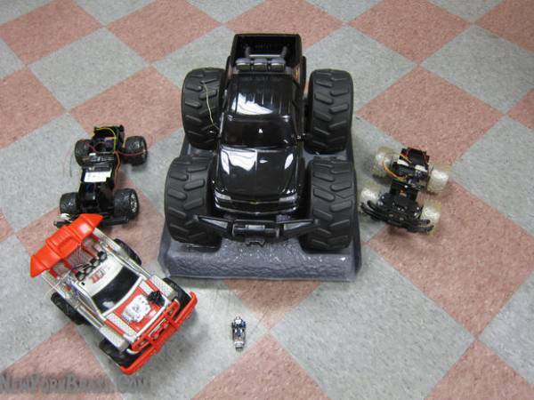
It suddenly occurred to me that almost any toy RC car might be using this or almost similar architecture. I opened up 4 RC cars that were donated to the project and indeed they all use more or less the same configuration: All these cars have 2 H-Bridges on a small board mounted inside. Almost all the cars these days use a variation on the RX2C toy car chip (link) (i.e. pins 6,7,10,11 are the drivers for H-Bridge) and these boards can accept logic voltage levels regardless of the battery voltages. The boards that do not use the chip will usually have an equivalent daughter board that fills the same function. Furthermore- the boards are optimized to drive the motors of the cars optimally. Contrary to the article they are safe to turn on both sides of the H-Bridge at the same time by mistake – all they do is turn on braking mode.
Almost all RC cars are configures so the rear wheels are running of a power H-Bridge for the forward/reverse motion and one H-Bridge is used to run a servo or servo-like mechanism in the front wheel. There is another configuration in which the right two wheels are connected to one motor and the left two wheels connected to another and this configuration can do some interesting stunts such as turning on the spot and other tricks.
The chip specifies an additional output – “turbo mode” however I am yet to see a car with this function implemented.
If you open you car and do not find the standard configuration – do not despair – figuring out the H-Bridge inputs are easy – and usually are the pins connected to 2.2k resistor.
The steps involved in making this work:
1) remove the RC chip – more on this later.
2) solder 4 wires to the H-Bridge Terminals
3) solder a wire to the negative terminal of battery – to power the arduino
4) solder a wire to the positive side of the switch – to power the arduino..
Here is a video of this mod after we completed the mod in 25 minutes.
Once reassembled, you can control the car from the arduino – and viola! you have a robotic car!
After doing a few cars – i find that the process of conversion of a car takes about 30-40 minutes.s a
Note the cars are sensorless!
VARIANTS:
* RX2C microchip based controller/receiver
* Daughter bvoard based controller/receiver
* Analog (transistor based) H-Bridge – can be used with analogWrite and PWM to control the power
* Relay based H-Bridge for the bigger devices. This can only be turned on and off – if you want to use PWM on there – you will have to turn to a custom H-Bridge design and ditch the board.
NOTE: This mod cancels the RC functionality. I have had thought to hack the RC part to allow two arduinos (or more) to communicate via hacking the transmitter and then connecting the (disconnected) signals lines as an arduino input. thus one would kill a few birds in one stroke: a dual H-Bridge, robotic car, and half duplex RC communications between arduinos. maybe I will tacle this in the future 🙂
WARNING: Make sure that the switch is off while programming your fully charged vehicle -or you will have a robotic missile flying off the table at maximum speed and power. Also you can expect some weak movement of the wheels due to the H-Bridge being powered by the USB cable – even when switch is off.
Here is a video of the kids programming their own cars by themselves, and also note the cars are sensorlesss
Step 1: Modifying a car from A-Z
These pictures show the beginning of the dismantleation.
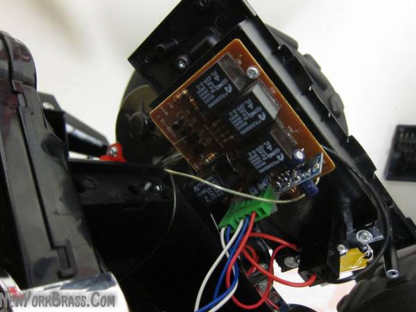
Step 2: A closer look at a hacked board
Here you can see chip was removed and that wires were installed instead
Note – some boards do not use a variant of the TC RX2C chip instead they will have a daughter board (the last picture in the set)
Also some boards do not use transistors for the H-Bridge but rather use micro relays.
222
Interfacing to through hole dips is easier than soldering carefully to surface mount pads. Also care must be taken not to strip the pads by pulling and wires should be secured to board using hot glue or by some other means.
Step 3: The disembowelment of the car
Step 9: Arduino code example
#define FWR 3
#define BACK 5
#define RIT 7
#define LEFT 9
void setup() {
// put your setup code here, to run once:
pinMode(FWR,OUTPUT);
pinMode(BACK,OUTPUT);
pinMode(RIT,OUTPUT);
pinMode(LEFT,OUTPUT);
}
void loop() {
// put your main code here, to run repeatedly:
analogWrite(FWR,100);
digitalWrite(RIT,HIGH);
delay(1000);
analogWrite(FWR,0);
digitalWrite(RIT,LOW);
delay(1000);
analogWrite(BACK,100);
digitalWrite(LEFT,HIGH);
delay(10000)
analogWrite(BACK,0);
For more detail: How to convert (almost) any 27 or 49 MHz RC Car into a Robotic car