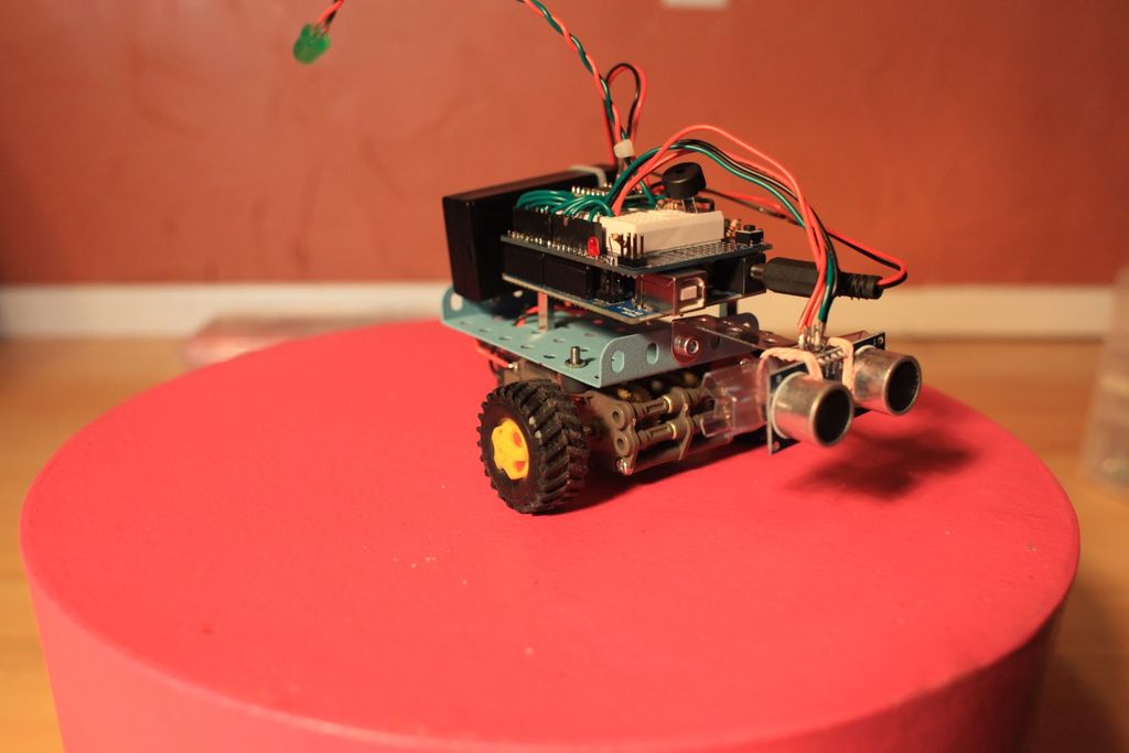
What is Clusterbot? He is a small, affordable, autonomous Arduino-powered robot. He can move, see, avoid obstacles, and makes a melodic chirping sound sometimes.
Clusterbot was my first Arduino project, and I think he makes a great project for a beginner. While building Clusterbot you will learn how to use motor controllers, ultrasonic rangefinders and how to program an elementary robotic platform. The most important thing I learned from building Clusterbot was the importance in planning the location of things like your Arduino board, battery packs, wiring, etc.
Why is it called Clusterbot? The more I worked on Clusterbot, the more I found my form following function than design. I ended up with wires everywhere, the battery pack extended off the back to maintain balance and a mess of erector set odds and ends. The end result was a cluster%#&@ of parts really, so I named him Clusterbot. No matter what the rest of him looks like, the ultrasonic sensors gave him a good looking face, and at least you could tell where the front was.
You don’t have to follow every step of the physical build, but I do recommend you pay close attention to the motor controller hookup and ultrasonic programming sections.
Let’s get started!
Here’s a video of a finished Clusterbot:
Step 1: Bill of Materials
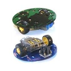
2. Pololu round robot chassis kit – $24 at http://www.robotshop.com/pololu-round-robot-chassis-kit-solid-blue-2.html
3. Pololu dual 1A motor driver – $8.45 at http://www.robotshop.com/productinfo.aspx?pc=RB-Pol-110&lang=en-US
4. Protoshield – $14.95 at http://www.robotshop.com/productinfo.aspx?pc=RB-Spa-303&lang=en-US
5. HC-SR04 Ultrasonic sensor – Buy these on ebay. You can get them for around $4 apiece instead of the $30 Parallax charges for their PING sensors.
6. Hookup wire and solder.
7. Battery holder for motor batteries. I bought a 2 AA pack from Radio Shack for a couple of bucks.
8. Two AA batteries and one 9 volt battery.
9. Various nuts, bolts, zipties and pieces of wood, plastic, etc. I used parts from an old erector set. Whatever you have laying around will be fine.
10. Optional – I added a big diffused green LED and a piezo buzzer to my Clusterbot to pimp it out a little. Buy a few noisy and shiny things to make your bot more interesting. The Pololu round robot chassis referenced above contains the motors, gearbox, axles, wheels, tires, caster and round plastic chassis. This is a pretty awesome deal for a first robot. The kit actually comes with two casters too.The protoshield is not essential – you may substitute your own breadboard instead. I used a protoshield because I had one sitting around. It does make your design a little cleaner however.
If you already have an Arduino and either don’t use or already have a protoshield, you can build Clusterbot for around $35. Buying everything listed above will come to around $70.
Step 2: Assemble the gearbox
Follow the instructions for the Tamiya gearbox assembly. I used the lower gear ratio instructions for my build. You can use the video below for reference.
Step 3: Assemble the ball caster
Two of them come in the kit – you only have to put one together.
Step 4: Solder headers to the motor driver
Solder the header pins to the motor driver breakout board. An easy way to do this – use a breadboard to hold everything together as shown in the video.
Step 5: Assemble chassis
Time to attach the wheels and tires and mount the gearbox and ball caster to the chassis.
Step 6: Solder hookup wire to motors
Solder hookup wire to the two terminals on each motor. Leave plenty of slack – these wires will connect to the motor driver on top of the robot. Strip, make a little hook in the wire, squeeze it to the terminal and solder. I used zipties for cable management.
Step 7: Mount Arduino, protoshield and motor driver to chassis.
Step 8: Understanding your motor driver!
It took a few hours of research and trial and error for me to figure out how to use the Toshiba TB6612FNG with my Arduino, but I finally figured it out. Hopefully I can save someone some trouble by posting all of the information here.
This information is referring to the Toshiba TB6612FNG , sold on breakout boards as the Sparkfun Motor Driver 1A Dual TB6612FNG and the Pololu Dual DC Motor Driver 1A. Refer to the picture for the rest of this step for pinout information.
A few TB6612FNG links:
TB6612FNG Motor Driver carrier overview at Robotshop.com
Toshiba TB6612FNG Datasheet
Forum post at the Pololu forum regarding using the TB6612FNG with Arduino.
At first I was under the impression that you just hooked up AO1 and AO2 to one motor, BO1 and BO2 to the other motor, and PWMA to one PWMA to one PWM output and PWMB to another PWM output. It turns out, you have to make every connection on the TB6612FNG chip to get it to work properly. I’ll cover them one by one.
From the top left of the diagram, working counter-clockwise:
GND – Connect to the ground terminal on the Arduino board
VCC – Connect to the 5V VCC on the Arduino board.
AO1 – Connect to the negative lead of motor A.
AO2 – Connect to the positive lead of motor A.
BO2 – Connect to the positive lead of motor B.
BO1 – Connect to the negative lead of motor B.
VMOT – Connect to the positive side of the power source you are using to power the motors.
GND – Connect to the negative side of the power source you are using to power the motors.
PWMA – Connect to PWM pin on the Arduino. On the Arduino Uno, this would be either pin 3,5,6,9,10,or 11.
AIN2 – Connect to a digital pin on the Arduino.
AIN1 – Connect to a digital pin on the Arduino.
STBY – Connect to a digital pin on the Arduino.
BIN1 – Connect to a digital pin on the Arduino.
BIN2 – Connect to a digital pin on the Arduino.
PWMB – Connect to a PWM pin on the Arduino. On the Arduino Uno, this would be either pin 3,5,6,9,10,or 11.
GND – Connect to the ground of the Arduino.
Now that you have the connections made, it is easy to use the controller to make your motors go. Basically, you make motor A move clockwise by setting AIN1 to HIGH, AIN2 to LOW, and sending a value between 1 and 255 to PWMA. STBY will need to be set HIGH also for any motor control to happen. Also, your mileage may vary, but I found that my motors would not function reliably unless I used a minimum PWM value of 35. This is probably a function of motor size, power source, robot weight, etc.
So, to go forward you would need to program:
STBY – HIGH
AIN1 – HIGH
AIN2 – LOW
PWMA – 255
STBY – HIGH
BIN1 – HIGH
BIN2 – LOW
PWMB – 255
Backwards would be the same as the above, except AIN1 and BIN1 would be LOW while AIN2 and BIN2 would be high.
So, the IN1 and IN2 pins determine direction, while the PWM pins control speed. You should be able to use this information to figure out how to do all sorts of turns and maneuvers.
Don’t forget the STBY pin must be high for the chip to work!