Summary of Zuno Line Follower using Arduino Uno with Proteus Simulation
The Zuno Line Follower is an Arduino Uno-based robot project designed to track a line using a Zumo-style model within a Proteus simulation. It utilizes a Zumo line sensor to detect position, calculating error against a center reference (2500) to adjust left and right motor speeds independently. This real-time control system employs proportional and derivative-style logic to correct drift, ensuring the robot stays on track while limiting speeds between 0 and 255. The project serves as an educational tool for embedded systems, robotics, and sensor-based navigation.
Parts used in the Zuno Line Follower:
- Arduino Uno
- Zumo robot / Zumo Turtle model
- Zumo line sensor module
- Zumo motor drive system
- Left and right DC motor drive outputs
- Zumo button
- LED and reset circuit
- I2C interface
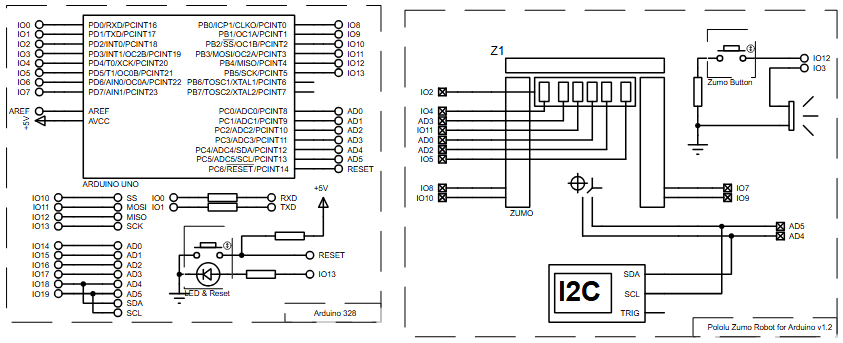
- Arduino digital pins (IO2, IO4, IO5, IO7, IO8, IO9, IO10, IO11, IO12, IO13)
- Arduino analog pins (AD0, AD2, AD3, AD4, AD5)
- Power and ground connections
Introduction
The Zuno Line Follower is an Arduino-based robot project designed to follow a line using a Zumo-style robot model. This microcontroller project uses an Arduino Uno with a Zumo line sensor and motor drive system inside a Proteus simulation. The robot reads the position of the line, calculates how far it has drifted from the center, and adjusts the left and right motor speeds to stay on track. It is a useful project for learning embedded systems, robot control, sensor-based movement, and practical electronics. Because the logic is built around line position feedback, it is also a good example of real-time control in DIY electronics.

How the Project Works
The project uses the Zumo line sensor to detect the position of the line under the robot. In the flowchart, the line sensor returns a value called linePosition. The controller calculates an error using:
error = linePosition - 2500This means the robot treats 2500 as the center reference point. The control logic uses the current and previous error to calculate a motor speed correction:
speedDifference = error / 4 + 6 * (error - lastError)This correction changes the left and right motor speeds:
leftSpeed  = maxSpeed + speedDifference
rightSpeed = maxSpeed - speedDifference
Workflow Explanation
Zumo Line Sensor
       ↓
Arduino Uno reads line position
       ↓
Calculate line error
       ↓
Calculate speed difference
       ↓
Generate left and right motor speeds
       ↓
Limit motor speeds between 0 and 255
       ↓
Drive Zumo left and right motors forward
Key Features
- Arduino Uno based line follower robot
- Designed for Proteus simulation
- Uses Zumo line sensor feedback
- Calculates line position error from a center reference value
- Uses proportional and derivative-style correction logic
- Controls left and right motor speeds independently
- Motor speed is limited between 0 and 255
- Uses forward drive control for both wheels
- Includes Zumo button and reset/LED section in the schematic
- Suitable for learning robotics, embedded systems, and sensor-based control
Components Used
- Arduino Uno
- Zumo robot / Zumo Turtle model
- Zumo line sensor module
- Zumo motor drive system
- Left and right DC motor drive outputs
- Zumo button
- LED and reset circuit
- I2C interface
- Arduino digital and analog pins (Digital: IO2-IO13, Analog: AD0, AD2-AD5)
- Power and ground connections
Applications
- Robotics education
- Embedded systems training
- DIY electronics projects
- Sensor-based robot navigation
- Mini autonomous vehicle experiments
- Line tracking demonstrations
- Motor control practice
- Proteus-based circuit diagram and firmware testing
- Control algorithm learning using real-time feedback
Explanation of Code Logic
No complete source code text was provided, but the supplied flowchart clearly shows the main firmware logic.
Setup Logic
lastError = 0
maxSpeed = 255
lastError stores the previous line error, while maxSpeed defines the maximum motor speed value.
Line Sensor Reading
readLinePos
linePosition
This gives the Arduino Uno a position value that tells where the detected line is relative to the robot.
Error Calculation
error = linePosition - 2500This is the main working principle of the project. The robot continuously corrects itself based on the sensor feedback.
Speed Difference Calculation
speedDifference = error / 4 + 6 * (error - lastError)This combines the current error with the change in error, helping the robot react quickly.
Motor Speed Generation
leftSpeed = maxSpeed + speedDifference
rightSpeed = maxSpeed - speedDifference
The robot turns left or right depending on the correction value.
Speed Bounding
if leftSpeed < 0: leftSpeed = 0
if rightSpeed < 0: rightSpeed = 0
if leftSpeed > maxSpeed: leftSpeed = maxSpeed
if rightSpeed > maxSpeed: rightSpeed = maxSpeed
Motor Drive Output
Left wheel  → FORWARDS → leftSpeed
Right wheel → FORWARDS → rightSpeed
No LCD, UART, temperature sensor, or separate display module is shown in the schematic.
Flowchart
Proteus Simulation
In the Proteus simulation, the Arduino Uno is connected to the Zumo robot model. The simulation represents a line follower system where the Zumo line sensor provides line position data to the Arduino. The Arduino processes that line position, calculates the correction value, limits the motor speeds, and drives the left and right Zumo motors forward. When the line position changes, the calculated speed difference changes too, causing the robot to correct its direction. This makes the simulation useful for testing the circuit diagram, motor control logic, sensor feedback, and firmware behavior before moving to physical hardware.
Conclusion
The Zuno Line Follower using Arduino Uno is a clean and practical embedded systems project for learning line tracking, sensor feedback, and motor control. Its Proteus simulation makes it easier to understand the working principle before testing on real hardware. With Arduino Uno, Zumo line sensing, and speed correction logic, this project is a useful starting point for robotics and DIY electronics learning.
Complete File
Zuno Line Follower using Arduino Uno with Proteus Simulation
- How does the robot calculate its position error?
The controller calculates error by subtracting the center reference value of 2500 from the current linePosition. - What formula determines the speed difference correction?
The formula used is speedDifference equals error divided by 4 plus 6 multiplied by the difference between current and last error. - Can the motor speeds exceed 255 in this project?
No, the firmware limits all motor speeds to remain strictly between 0 and 255. - Which microcontroller is used for this line follower robot?
The project uses an Arduino Uno microcontroller. - Does the robot use forward drive control for both wheels?
Yes, the schematic and workflow indicate forward drive control is used for both the left and right wheels. - What is the primary purpose of the Proteus simulation in this project?
The simulation allows users to test the circuit diagram, motor control logic, and firmware behavior before moving to physical hardware. - How are the left and right motor speeds adjusted based on drift?
If the robot drifts, one motor slows down while the other speeds up to turn the robot back toward the line. - Are LCD or UART display modules included in the schematic?
No, no LCD, UART, temperature sensor, or separate display module is shown in the provided schematic or flowchart.